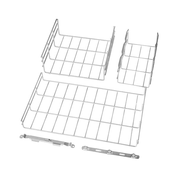
Explaining NEC Article 392 on Cable Trays
For the installation of single conductor cables sized 1/0 AWG to 4/0 AWG in industrial establishments, the NEC specifies the maximum allowable rung spacing for the cable tray.
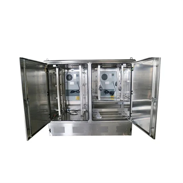
Electrical Manholes: A Guide for Engineers
• Internal space: Typically ≥ 2×2 m for medium voltage. • Spacing between manholes: • Residential low voltage: every 50–100 m. • Industrial: 150–250 m.
Manhole Conduit Layout – Spacing & NEC Compliance Concerns
The issue is that all conduits must enter from one side of the manhole, and I need to ensure proper spacing, staggering, NEC compliance, and constructability—all while working within a
Cable Tray Fill Rules (NEC 392)
Support spacing: NEC 392.18 requires cable trays to be supported at intervals consistent with the manufacturer''s installation instructions, but not more than the maximum span listed for the
Cable Tray Support Spacing: Key Guidelines Explained
Explore the essential cable tray support spacing requirements for safe and efficient installations. Learn NEC guidelines for perforated, ladder, and wire mesh trays.
A Guide to Installing and Supporting Electrical Cable Trays
Cable Tray Support Span: The distance between supports is a critical calculation. The cable tray support span must be determined based on the manufacturer''s load capacity chart and the total anticipated
NEC Article 392 Guide: Ensuring Compliance for Cable Tray Systems
A cable tray is a support structure that seems to be a bridge that supports wires in the air. The significance of this difference is that it varies the type of wires that can be employed.
Electrical Manhole Design Guidelines | PDF | Electric Power
The document outlines the design specifications for manholes used in electrical systems, including calculations for conduit sizes and the required number of conduits based on cable dimensions.
Cable Tray Questions | Cable Tray Institute
Answer: The NEC does not have a specific installation clearance, but indicates in section 318-6 (b) that cable trays should be exposed and accessible. Telecommunications standard TIA/EIA-569
Cable Tray Dimensions and Specifications as per NEC
Proper cable tray: A simple method for determining the correct cable tray width is to calculate the cable tray widths needed for each of the cable configurations per steps (2) and (3).
Optical Power Meters & Sources
High-precision power meters (Ge/InGaAs) and stabilized light sources for insertion loss and return loss testing.
OTDR & Fiber Characterization
Full-featured OTDR, fiber OTDR testers, and modular OTDR test modules for network deployment and troubleshooting.
OSA & Eye Diagram Analyzer
High-resolution OSA for DWDM and eye diagram testers for signal integrity validation.
BERT & Endface Inspection
BERT up to 800G, fiber endface inspection probes, and extinction ratio meters for comprehensive testing.