
GUIDE CABLE TRAYS TECHNICAL
When fitting cable trays and their accessories, the products are cut on site to create changes of direction, adjust sections, etc. Damage can also occur during handling; as a result, both the
B-Line series Cable Tray Design Considerations
Cable tray must be capable of supporting not just the weight of the cable, but also the weight of any equipment or materials attached to the cable tray. Additionally, dynamic environmental elements
Aluminum Channel Horizontal Elbows 30°
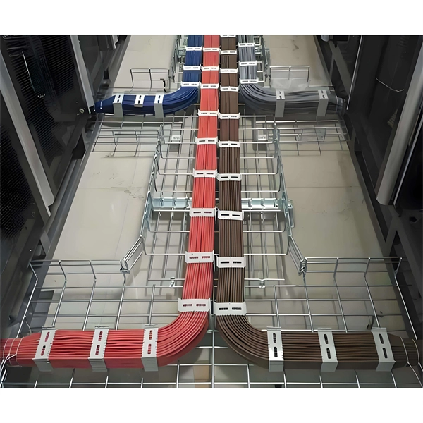
Channel cable tray secures cables using Eagle Basket pre-punched holes. New pre-punched holes allow the secure attachment of cables to the inside of the channel without the need to drill holes,
Cable Tray Bend Calculator
For a 30-degree offset, the distance between bends (hypotenuse) is calculated as Offset Distance × Cosecant (30°), which equals Offset × 2. The total length of tray used increases slightly due to the
6A-36-30HB36 | Eaton B-Line series horizontal bend | Specifications
Authenticated: The product is verified as being authentic; however, this does not guarantee the condition or fit for purpose of the product. Note: If file (s) are missing from the .zip download then the file type is
Easy Step to Make Cable tray 30 Degree Offset Formula
Easy step to making cable tray offset bend 30 degrees at a distance of 150 mm +150 mm = 300mm.more
Vertical Outside 30 Elbow | Ladder Trays | Cable Tray and Reels
The aluminum I-beam design of ITray is perfect for industrial installations with large diameter cables in long span situations, minimizing total tray width and creating a smooth transition between straight
Cable Bending Radius in Cable Tray | Information by Electrical
If you do it like shown, you really limit the capacity of the tray because of the cable bending radius. The cutting and field fabrication of what you show would probable cost more than using the
cable tray and trunking for electricians (Page 1) / Help
When folded the top will run from D to E and the bottom G to C to F to H. The dotted lines show where the strip is folded. Of course, the strip doesn''t
Cable Tray Conductor Sizing Guide
Tray cable is a listed cable type, often marked TC or TC-ER, designed for installation in cable tray under its listing and the applicable NEC wiring method rules. Ampacity is the maximum
cable tray and trunking for electricians (Page 1) / Help Me ! / Math Is
When folded the top will run from D to E and the bottom G to C to F to H. The dotted lines show where the strip is folded. Of course, the strip doesn''t look like the diagram (as it is straight) but,
Optical Power Meters & Sources
High-precision power meters (Ge/InGaAs) and stabilized light sources for insertion loss and return loss testing.
OTDR & Fiber Characterization
Full-featured OTDR, fiber OTDR testers, and modular OTDR test modules for network deployment and troubleshooting.
OSA & Eye Diagram Analyzer
High-resolution OSA for DWDM and eye diagram testers for signal integrity validation.
BERT & Endface Inspection
BERT up to 800G, fiber endface inspection probes, and extinction ratio meters for comprehensive testing.