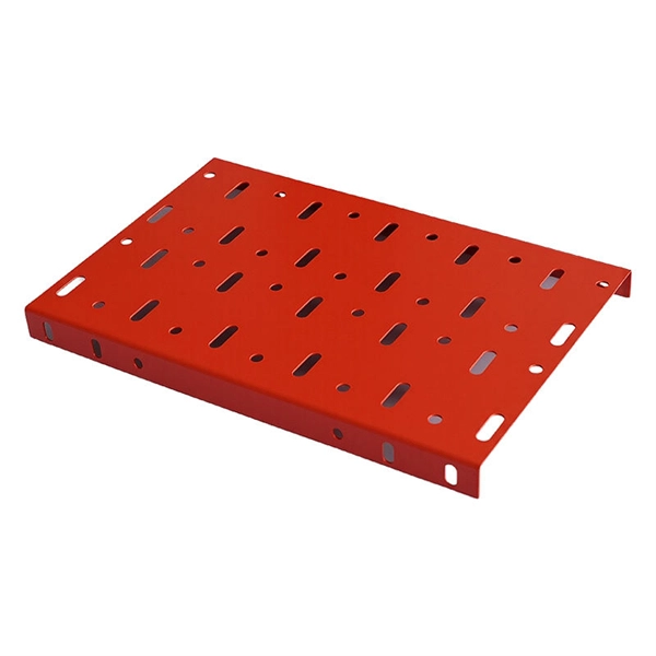
Ladder Trays | Cable Tray and Reels | Wire and Cable Management
Refers to the approximate height of a cable tray used for specifying. Selecting a specific height will show cable trays with that height, as well as cable tray accessories compatible with that height.
GUIDE CABLE TRAYS TECHNICAL
When fitting cable trays and their accessories, the products are cut on site to create changes of direction, adjust sections, etc. Damage can also occur during handling; as a result, both the
Cable Tray Technical Guide A practical guide to product selection
Cable tray length is selected based on the load to be supported, the distance between the supports (also referred to as the span), and handling and installation constraints.
LEGRAND CABLE TRAYS TECHNICAL GUIDE
When fitting cable trays and their accessories, the products are cut on site to create changes of direction, adjust sections, etc. Damage can also occur during handling; as a result, both the
Cable Tray Installation Guidelines | PDF | Galvanization
The document outlines steps for laying cables, including installing supports, fixing the tray, laying cables with proper spacing, and tying them with cable ties.
Cable Tray Spacing Standards for Installation and Safety
Discover the essential cable tray spacing requirements for safe and efficient installation. Learn key standards, horizontal and vertical spacing, and more.
Cable Tray Installation Rules (NEC 392) – Electrical Trader
Generally, standard trays require supports every 6 to 10 feet, while heavy-duty, long-span trays can handle distances of up to 20 feet between supports. To determine the proper spacing,
Cable Tray Support Spacing: Key Guidelines Explained
Explore the essential cable tray support spacing requirements for safe and efficient installations. Learn NEC guidelines for perforated, ladder, and wire mesh trays.
Core Principles for Electrical and Instrumentation Cable
Spacing Standards: Electrical (power) and instrumentation (signal/control) cable trays should maintain a minimum vertical and horizontal distance. Industry
IEC Standard for Cable Tray: Complete Technical Guide
Trays should be installed with correct support spacing, using compatible accessories. Overloading must be avoided, and all bends or junctions should maintain minimum cable bend radius.
Guide to cable support systems
With regard to the cable support lengths, the manufactur-er must provide information on the limit values for the final support spacing, position and type of the connection with-in the span width as well as the
Optical Power Meters & Sources
High-precision power meters (Ge/InGaAs) and stabilized light sources for insertion loss and return loss testing.
OTDR & Fiber Characterization
Full-featured OTDR, fiber OTDR testers, and modular OTDR test modules for network deployment and troubleshooting.
OSA & Eye Diagram Analyzer
High-resolution OSA for DWDM and eye diagram testers for signal integrity validation.
BERT & Endface Inspection
BERT up to 800G, fiber endface inspection probes, and extinction ratio meters for comprehensive testing.