Avoiding Mistakes in Instrumentation Cable Tray
Use the right sort of tray, keep the support spacing between 1.5 and 2 meters, separate the power, control, and instrumentation cables, and make sure the grounding and bonding are done
Minimum Space Between Power & Instrument Cables
You have not referred whether the Instrument Cable - is shielded type or not shielded type. If it is shielded type a gap of 300 MM is sufficient. The shield should be earthed on one end
Electrical / Insrumentation trays separation distance | Eng-Tips
The NEC does require that all cables in a common tray, conduit etc must be insulated up to the highest voltage in use. So if you run 480 V circuits in the tray, everything else must be
Cable Tray Spacing Standards for Installation and Safety
Discover the essential cable tray spacing requirements for safe and efficient installation. Learn key standards, horizontal and vertical spacing, and more.
Cable tray separation | Automation & Control Engineering Forum
Instrumentation trays should always be at the bottom. At least 12 inches of clear space should be provided between tray levels. We also add that instrument trays cross electrical trays at 90
Instrument Location Layout and cable routing layout – InstruNexus
The Depth Rule: Electrical codes typically specify that the maximum outside diameter of any cable within the tray must not exceed a certain percentage of the tray''s internal depth.

B-Line series Cable Tray Design Considerations
When supporting small diameter multi-conductor control and instrumentation cables, 6, 9, or 12-inch rung spacings should be specified.
Core Principles for Electrical and Instrumentation Cable Tray Layouts
Spacing Standards: Electrical (power) and instrumentation (signal/control) cable trays should maintain a minimum vertical and horizontal distance. Industry standards often recommend at least 300mm (12
Cable Tray Support Spacing: Key Guidelines Explained
Explore the essential cable tray support spacing requirements for safe and efficient installations. Learn NEC guidelines for perforated, ladder, and wire mesh trays.
Cable Tray Technical Guide A practical guide to product selection
Cable tray length is selected based on the load to be supported, the distance between the supports (also referred to as the span), and handling and installation constraints.
Cable Tray Installation Rules (NEC 392) – Electrical Trader
Core rules for selecting, installing, grounding, and filling cable trays—clearances, materials, separation, and bonding explained.
Optical Power Meters & Sources
High-precision power meters (Ge/InGaAs) and stabilized light sources for insertion loss and return loss testing.
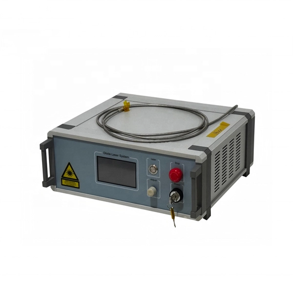
OTDR & Fiber Characterization
Full-featured OTDR, fiber OTDR testers, and modular OTDR test modules for network deployment and troubleshooting.
OSA & Eye Diagram Analyzer
High-resolution OSA for DWDM and eye diagram testers for signal integrity validation.
BERT & Endface Inspection
BERT up to 800G, fiber endface inspection probes, and extinction ratio meters for comprehensive testing.