Best practice guide to cable ladder and cable tray
The following recommendations are intended to be a practical guide to ensure the safe and proper installation of cable ladder and cable tray systems
Supporting MC cable with Cable Tray | Page 2 | Information by
In Canada, the CEC rule 12-2200 details the requirements. With cables less then 50mm in diameter in a tray, the minimum vertical clearance is 150mm between trays. With cables greater then
Beama Best Practice Guide | Installation Of The System | Cable
Cable ladders and cable trays should be mounted far enough off the floor or roof to allow the cables to exit through the bottom of the cable ladder or cable tray.
How do crossarms work in a distribution network?
I''m a supplier of crossarms, and today I''m gonna dive into how crossarms work in a distribution network. It''s a topic that might not sound super exciting at first, but trust me, it''s pretty crucial for keeping our
The Ultimate Guide to Electrical Cross Arms for Power
Electrical cross arms, also known as braces or traverses, are vital components of overhead transmission and distribution lines. They serve as support structures for insulators, conductors, and other electrical
Your Electrical Crossarm Product Primer
Insert the crossarm pin – insert the threaded end of the crossarm pin through the hole in the crossarm. Secure the crossarm pin – thread the non-pointed end of
Best Practice Guide to Cable Ladder and Cable Tray Systems
This publication is intended as a practical guide for the proper and safe* installation of cable ladder systems, cable tray systems, channel support systems and associated supports.
Galvanized Crossarms for Cable Trays: Analysis of Functions,
Galvanized crossarms for cable trays are typically made of Q235 low-carbon steel via rolling. Their cross-sectional forms are mostly U-shaped or L-shaped, and their thickness is classified
Chapter 13: Insulators, Crossarms, and Conductor Supports
Special clays are selected and mixed mechanically until a plastic-like compound is produced. The clay is then placed in molds to form the insulators. The molds are placed in an oven to dry the clay. When
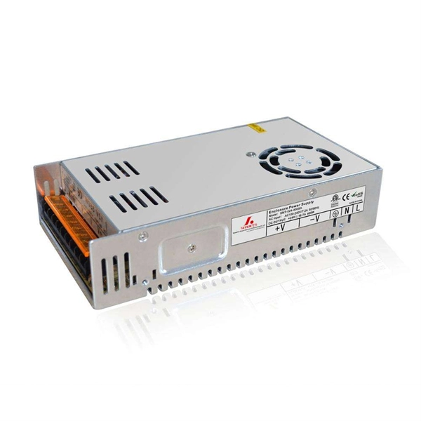
Introduction to NVIDIA DGX B300 Systems
The DGX B300 can be powered in two ways: using a busbar or a traditional data center power distribution unit (PDU) connected to the power supplies. Busbar version: Includes a clip at the back
Cable Tray Technical Guide A practical guide to product selection
Cable tray length is selected based on the load to be supported, the distance between the supports (also referred to as the span), and handling and installation constraints.
Modeling Cross Arms in PLS-POLE
One way to model this is to use short cross arm elements, but to fix both ends. Another way, shown in the model, is to create a cross arm component with the built up section properties of both cross arms.
A Guide to Installing and Supporting Electrical Cable Trays
This guide covers the critical steps, from selecting the right electrical cable tray and performing accurate cable fill calculations to managing a safe cable pull through and ensuring all bonding and grounding
How to Bend Cable Tray Students trading aid on how best to put an
Includes a full demonstration on how bend steel cable tray using a bending machine and how to use a crimping to. You can buy a manufactured 90 degree bend or make one on a cable tray bending machine but in this video I
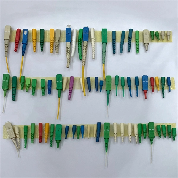
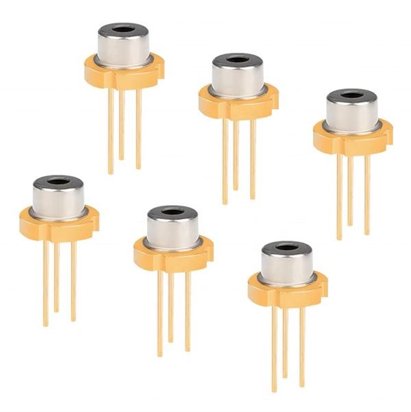
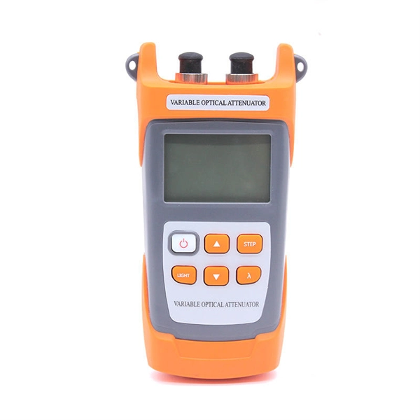
Optical Power Meters & Sources
High-precision power meters (Ge/InGaAs) and stabilized light sources for insertion loss and return loss testing.
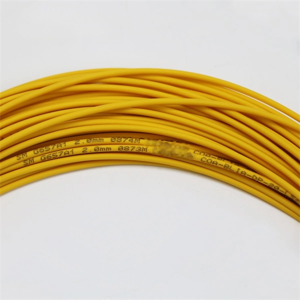
OTDR & Fiber Characterization
Full-featured OTDR, fiber OTDR testers, and modular OTDR test modules for network deployment and troubleshooting.
OSA & Eye Diagram Analyzer
High-resolution OSA for DWDM and eye diagram testers for signal integrity validation.
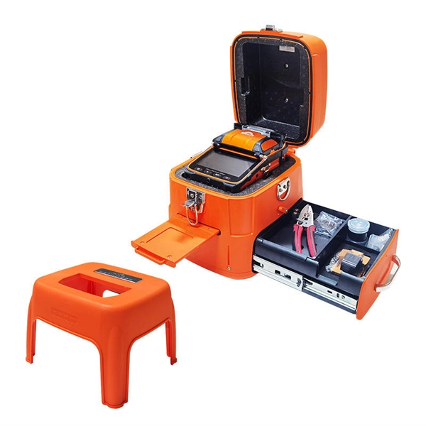
BERT & Endface Inspection
BERT up to 800G, fiber endface inspection probes, and extinction ratio meters for comprehensive testing.