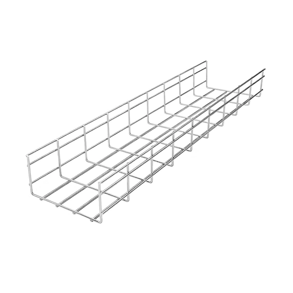
Cable Tray Support Spacing: Key Guidelines Explained
The NEC requires that cable trays must be supported by members at an interval specified by the cable tray manufacturer, but not more than 5 feet for horizontal runs to support the weight of
5 Steps to Learn How to Install Cable Trays
Check Regulations: Consult the National Electrical Code (NEC) or your local regulations regarding cable tray fill ratios (usually max 50%) and support spacing (typically every 1.5m to 2m).
Cable Tray Installation Guidelines
It includes diagrams showing how to mount cable trays on walls using pre-fabricated flanges or channels. The document outlines steps for laying cables, including installing supports, fixing the tray,
How to Fix Common Cable Management Issues using Cable Tray
How far apart should cable trays be supported? Depending on cable weight, tray material, installation conditions, and environmental load e.g., wind or vibration the advised distance between
Product Advice: Bracket Spacing Considerations
Traditionally, it has been recommended to install brackets approximately every 1 to 1.5 meters along the length of the cable tray. However, this guideline isn''t set in stone. There are factors to consider when
Cable Tray Installation
Use the right cable tray conduit clamps and brackets for wall, ceiling, or floor support. Make sure supports are spaced properly, typically 1.5 to 3 meters apart, depending on tray type and
What are the standard requirements of the cable tray bracket, and the
Bridge bracket when the wires in the cable tray are laid vertically, the cable wires should be fixed on the bracket of the bridge tray at an interval of 1.5 meters. When laying horizontally, it should be fixed at
NEC Article 392 Guide: Ensuring Compliance for Cable Tray Systems
Strong hangers or brackets should be used to ensure that cable trays do not fall or hang. According to the regulations under NEC 392.30, these supports have to be put at a consistent
Cable tray installation requirements-ZM Technology Co., Ltd.
(1) When the cable tray enters the building from the outside, the outward slope of the tray shall not be less than 1/100. (2) When the cable tray crosses with the electrical equipment, the clear
Proper Bracket Spacing for Cable Installations | CMW
When it comes to how much spacing there should be between brackets, the general rule of thumb is every 300mm to 400mm for horizontal runs, and 500mm to 600mm for vertical runs, but
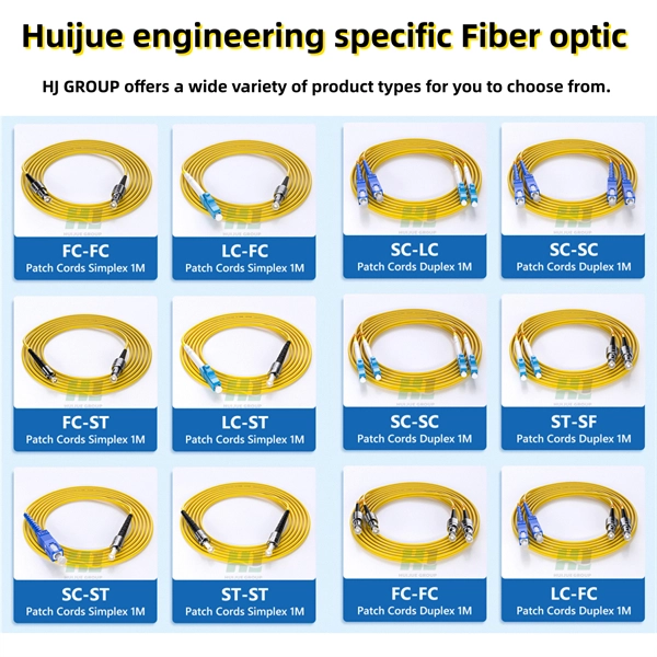
Optical Power Meters & Sources
High-precision power meters (Ge/InGaAs) and stabilized light sources for insertion loss and return loss testing.
OTDR & Fiber Characterization
Full-featured OTDR, fiber OTDR testers, and modular OTDR test modules for network deployment and troubleshooting.
OSA & Eye Diagram Analyzer
High-resolution OSA for DWDM and eye diagram testers for signal integrity validation.
BERT & Endface Inspection
BERT up to 800G, fiber endface inspection probes, and extinction ratio meters for comprehensive testing.