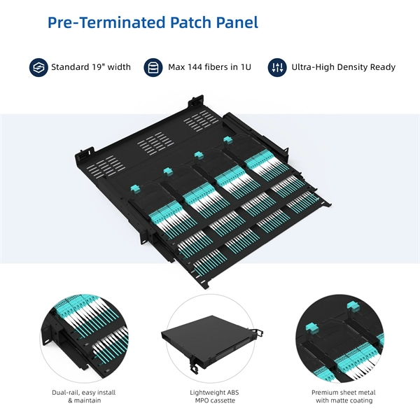
Patch Panels: A Complete Guide
Patch panels are usually designed to be fitted into standard 19-inch racks, with particular mounting hardware on the left and right-hand sides allowing for easy installation of one or multiple
Printable Patch Panel Label Diagram
I recently installed a patch panel at home so I could properly begin the process of retrofitting the place with a decent network infrastructure. When it came to labeling the patch panel
Understanding an Ethernet Patch Panel Diagram
The patch panel diagram helps technicians and network administrators understand the layout of the patch panel and the connectivity between different devices. In an Ethernet patch panel diagram,
What is a Patch Panel, and What is It Used For?
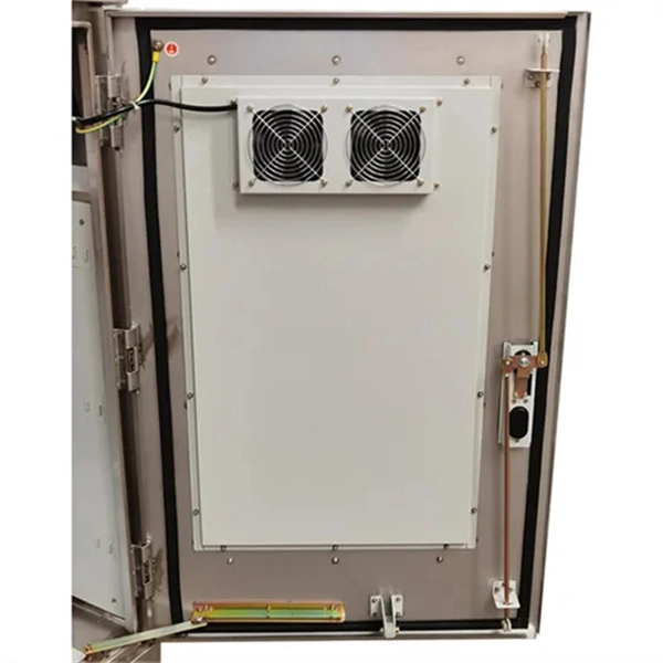
Patch panels are how network administrators avoid tangled knots of CAT5 cable across the Local Area Network (LAN) shack. As shown in the diagram below, a patch sits within the
Network Patch Panel Wiring Diagram
This comprehensive guide will provide all the information one needs to know about network patch panel wiring diagrams, and ensure that the installation process is successful.
cabling
I would diagram out the network from a layer2/3 perspective and go through the patch panels and physically label everything including the patch panel and the cables.
How to Wire a Cat5e Patch Panel?
This article explains the Cat5e patch panel wiring basics (T568A/T568B), required tools and materials, and step-by-step termination, including a patch panel wiring diagram reference.
Patch Panels: A Complete Guide
A patch panel connection diagram documents the physical connections between network devices mapped to a logical network diagram. It''s a visual representation of the physical layer of a
5 Essential Patch Panel Connection Diagrams for Optimal Network
A patch panel connection diagram documents the physical connections between network devices mapped to a logical network diagram. It''s a visual representation of the physical layer of a
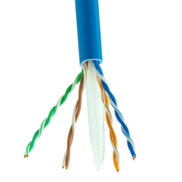
cabling
I would diagram out the network from a layer2/3 perspective and go through the
T568b Patch Panel Wiring Diagram
Learn the proper way to wire a T568B patch panel using a wiring diagram. Ensure a clean and efficient Ethernet network for your home or office.
Connecting the Dots: Understanding Patch Panel
Learn how to create and understand patch panel connection diagrams for efficient network management and troubleshooting.
Optical Power Meters & Sources
High-precision power meters (Ge/InGaAs) and stabilized light sources for insertion loss and return loss testing.
OTDR & Fiber Characterization
Full-featured OTDR, fiber OTDR testers, and modular OTDR test modules for network deployment and troubleshooting.
OSA & Eye Diagram Analyzer
High-resolution OSA for DWDM and eye diagram testers for signal integrity validation.
BERT & Endface Inspection
BERT up to 800G, fiber endface inspection probes, and extinction ratio meters for comprehensive testing.