Understanding an Ethernet Patch Panel Diagram
The patch panel diagram helps technicians and network administrators understand the layout of the patch panel and the connectivity between different devices. In an Ethernet patch panel diagram,
What is a Patch Panel: Why They Matter and How to Choose
With it, changes happen at the front of a rack in seconds, without touching a single installed cable. This guide explains what a patch panel is, how it works, the main types available, and what to consider
What Is a Patch Panel? Why It''s Important for Network Setup
Learn what a patch panel is, why it''s essential for structured cabling, and how it helps organize your network. I''ll show you the front ports, rear terminations, and explain how it all...
What is a Patch Panel, and What is It Used For?
A patch panel is an important network component that aids in the connection, organization, and overall management of network cables. Let''s talk about what a patch panel exactly
Patch Panels Explained: Types, Benefits, and How They Work
Patch panels function as the connection point between permanent cabling and active network devices. Horizontal or backbone cables are terminated on the rear of the panel, while short
How Does a Patch Panel Work?
On the front of the panel, there are corresponding ports. You use short, flexible cables (called patch cables) to connect these ports to switches, routers, or other network devices.
What Does a Patch Panel Do? Network Cabling Essentials
Patch panels serve as the critical interface between permanent horizontal cabling (running through walls and ceilings) and active network equipment, such as switches and routers.
Switch and Patch panel setup
If you have an existing patch panel the short answer to “can I just plug in a cable into the front of it” is yes. Patch panels aren''t so difficult to understand but might be a little intimidating at first
What Is a Patch Panel? A Complete Network Guide
Front side: where patch cords connect to switches or routers. This setup lets technicians reconfigure connections or swap equipment without disturbing the main wiring backbone. Because
Patch Panels: A Complete Guide
In each case, the patch panel has a number of RJ45 connectors on the front-facing side of the panel, and on the rear, color-coded IDC termination blocks.
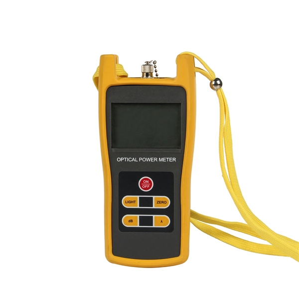
Optical Power Meters & Sources
High-precision power meters (Ge/InGaAs) and stabilized light sources for insertion loss and return loss testing.
OTDR & Fiber Characterization
Full-featured OTDR, fiber OTDR testers, and modular OTDR test modules for network deployment and troubleshooting.
OSA & Eye Diagram Analyzer
High-resolution OSA for DWDM and eye diagram testers for signal integrity validation.
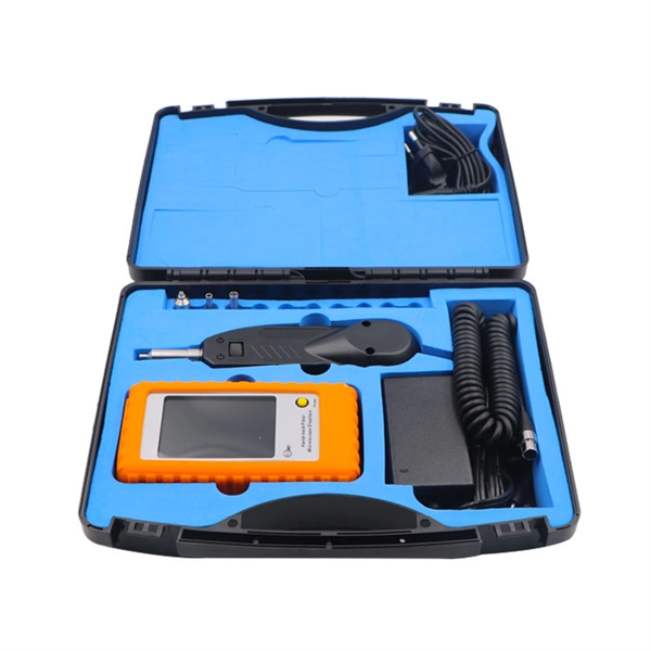
BERT & Endface Inspection
BERT up to 800G, fiber endface inspection probes, and extinction ratio meters for comprehensive testing.