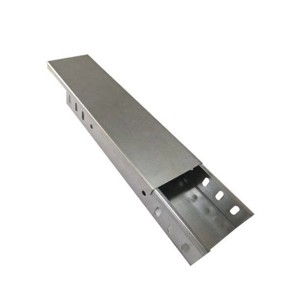
Cable Tray Design, Layout, and Overall Wiring Planning
Learn about effective Cable Tray Design and Layout for electrical systems. Our guide covers planning, material choice, safety, and maintenance.
CABLE TRAY SYSTEMS GUIDE
Some applications may require the cable tray to support the weight of a single, dead object in addition to the cable loads. Specifications typically require this to be applied at the midpoint of the span between
LEGRAND CABLE TRAYS TECHNICAL GUIDE
Not all cable trays are equivalent. The mechanical and electrical characteristics, tests, certifications, overall quality management, recommendations mentioned in this technical guide only apply to our
Guide to cable support systems
The load capacity of the cable trays according to the support width can be read off in the diagram using load curves – here, shown as an example for a cable tray with the tray widths 100 to 600 mm.
GUIDE CABLE TRAYS TECHNICAL
cable trays are equivalent. The mechanical and electrical characteristics, tests, certifications, overall quality management, recommendations mentioned in this technical guide only apply to our own cable
Full cable tray systems specification document
The drawings which constitute a part of these specifications indicate the general route of the cable tray systems. Data presented on these drawings is as accurate as preliminary surveys and planning can

Cable Tray Technical Guide A practical guide to product selection
Cable tray length is selected based on the load to be supported, the distance between the supports (also referred to as the span), and handling and installation constraints.
B-Line series Cable Tray Design Considerations
Cable tray must be capable of supporting not just the weight of the cable, but also the weight of any equipment or materials attached to the cable tray. Additionally, dynamic environmental elements
Cooper B-Line
Cooper B-Line has recognized the need for a complete cable tray reference source for electrical engineers and designers. The following pages address the 2011 National Electric Code®
Cable Tray Systems: Requirements and Best Practices
This article explains the main requirements and good practices for cable tray systems, including tray types, materials, loading, supports, bonding, cable selection, and installation details.
A Guide to Installing and Supporting Electrical Cable Trays
This guide covers the critical steps, from selecting the right electrical cable tray and performing accurate cable fill calculations to managing a safe cable pull through and ensuring all bonding and grounding
Cable Tray Layout and Design Standards
This document provides guidelines for cable tray layout and designations. It includes diagrams of typical cable tray layouts and fittings with metric dimensions.
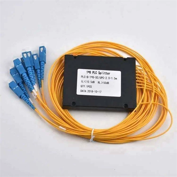
Optical Power Meters & Sources
High-precision power meters (Ge/InGaAs) and stabilized light sources for insertion loss and return loss testing.
OTDR & Fiber Characterization
Full-featured OTDR, fiber OTDR testers, and modular OTDR test modules for network deployment and troubleshooting.
OSA & Eye Diagram Analyzer
High-resolution OSA for DWDM and eye diagram testers for signal integrity validation.
BERT & Endface Inspection
BERT up to 800G, fiber endface inspection probes, and extinction ratio meters for comprehensive testing.