Cable Tray Technical Guide A practical guide to product selection
Cable tray length is selected based on the load to be supported, the distance between the supports (also referred to as the span), and handling and installation constraints.
Complete cable tray manual for electrical engineers and designers
Change is a complex problem when conduit banks are involved. The final drawings for a cable tray wiring system may be completed and sent out for bid or construction more quickly than for a conduit
Cable Tray Installation Guidelines | PDF | Galvanization
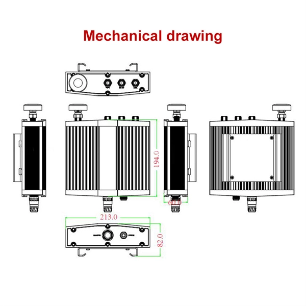
This document provides details on installing cable trays and their support systems. It includes diagrams showing how to mount cable trays on walls using pre-fabricated flanges or channels.

CABLE TRAY SYSTEMS GUIDE
The total load supported by the cable tray, uniformly distributed. This will be the combined weight of all of the cables or tray contents, any environmental loads (snow, ice, dust) and any concentrated static
KINETICS™ Seismic & Wind Design Manual Section
vertical force is 1.73 times the horizontal force. The net result is that for cable systems or for struts loaded in tension, the uplift force at the bottom end of the restraint can be considerably .
Cable Loads
The calculator is based on an iterative algorithm where the parable shaped cable is adapted to span L, height h1 and h2 according the figure above. The parable
Phase Sequence and Cable Arrangement
Ensuring that the balanced current goes through all cables is possible by the right phase sequence and the correct arrangement of the cables, given the magnetic
Document DICOS
A channel cable tray can be added to an existing cable tray system using the method illustrated in Figure 3-89 to add approved cabling systems. Refer to the loading information of the existing cable
Cable tray manual
Where the cable type may be used, cable tray may be installed to support it except as per Section 392.12 which states that cable trays shall not be installed in hoistways or where subject to severe
Best Practice Guide to Cable Ladder and Cable Tray Systems
Cables should be fastened to the cable ladder and/or cable tray using cable cleats or cable ties to prevent movement of the cables under normal use and during fault conditions (Figures 25a and 25b).
Phase Sequence and Cable Arrangement Configurations | Prysmian
Ensuring that the balanced current goes through all cables is possible by the right phase sequence and the correct arrangement of the cables, given the magnetic field interaction and impedances between
Cable Pulling Guide
Excessive pulling force or tight bends can cause internal damage that may not be visible but will affect performance. Protecting the cable during
INSTALLATION GUIDE
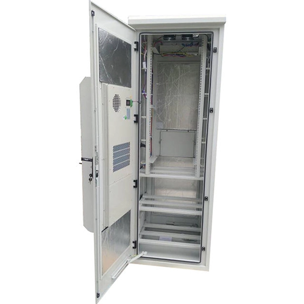
All tray items whether stored outside or indoors, should be placed on sufficient dunnage to enable future mechanical lifting. Trays and fittings should be stacked by their physical dimensions (width) and type.
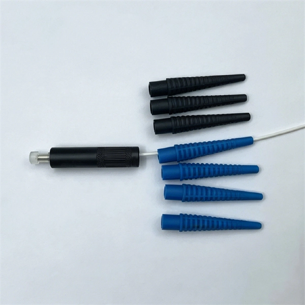
Optical Power Meters & Sources
High-precision power meters (Ge/InGaAs) and stabilized light sources for insertion loss and return loss testing.
OTDR & Fiber Characterization
Full-featured OTDR, fiber OTDR testers, and modular OTDR test modules for network deployment and troubleshooting.
OSA & Eye Diagram Analyzer
High-resolution OSA for DWDM and eye diagram testers for signal integrity validation.
BERT & Endface Inspection
BERT up to 800G, fiber endface inspection probes, and extinction ratio meters for comprehensive testing.