The FOA Reference For Fiber Optics
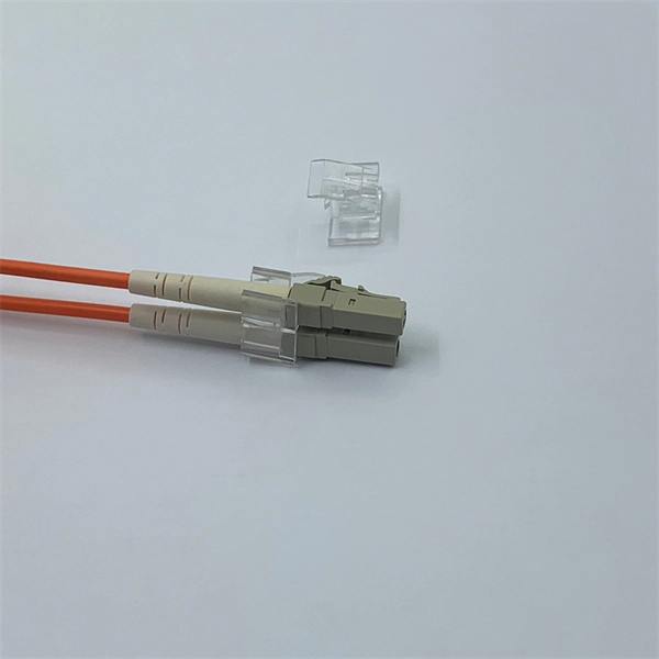
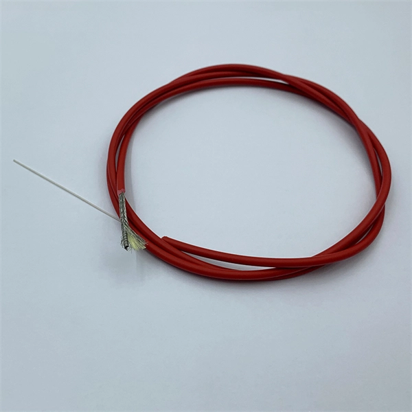
Most field singlemode terminations are made by splicing a factory-made pigtail onto the installed cable rather than terminating the fiber directly as is commonly done with multimode fiber.
Fiber Optic Pigtail: The Complete Guide to Types, Splicing Methods
Confused about fiber optic pigtails—which connector type, which polish, fusion or mechanical splice? Our guide covers LC vs SC, APC vs UPC, splicing methods, and real-world use
How to Splice Fiber Optic Pigtails: A Step-by-Step Guide
Master the art of fiber termination. Learn how to splice fiber optic pigtails using fusion splicing, follow the color code, and ensure low insertion loss.
The Complete Step-by-Step Guide to Fiber Optic Splicing
In this guide, we cover the basics of fiber optic splicing, how to perform splicing using two different methods, and finally some best practices to perform good fiber splicing.
Fiber Optic Splicing: Examining the Factors that Affect
Learn the the intrinsic and extrinsic factors that can impact fiber optic splice performance and how you can create the best fiber optic network.
Fiber Optic Cable Splicing Methods: A Practical Guide
The two primary industry-accepted methods for fiber optic cable splicing are fusion splicing and mechanical splicing. The choice between them depends on performance requirements,
Guide for splicing of fiber optic fibers | EFB-Elektronik
During the splicing process, two fiber optic cables are seamlessly joined by thermal fusion. This usually takes place in a fully automated process carried out by a splicer: The pigtails and installation cables
Fiber Optic Cable Splicing Explained
The common application for splicing is jointing cables in long outside plant cable runs. This is where a length of a run requires more than one cable. Splicing is generally used to terminate
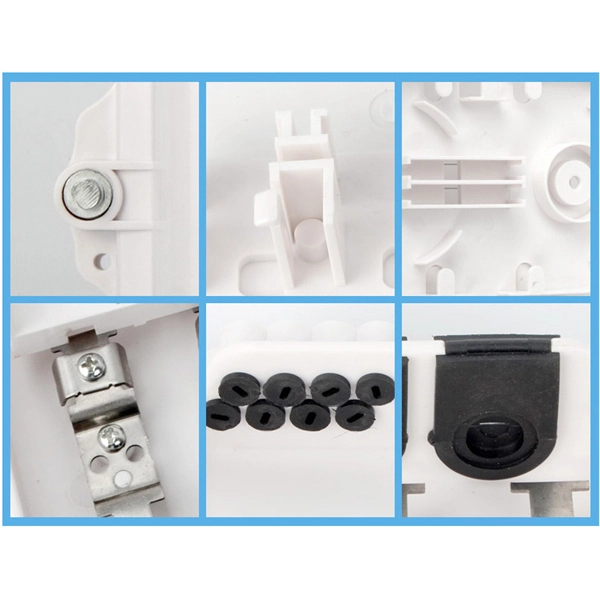
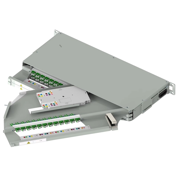
Fiber cable termination
Fiber Optic cable termination is the addition of connectors to each optical fiber in a cable. The fibers need to have connectors fitted before they can attach to other equipment. Two common solutions for
Understanding Fiber Termination Techniques: Splicing vs. Connectors
Fiber optic networks are the backbone of modern communication systems, enabling high-speed data transfer and reliable connectivity. When deploying fiber optic cabling, one of the most
Optical Power Meters & Sources
High-precision power meters (Ge/InGaAs) and stabilized light sources for insertion loss and return loss testing.
OTDR & Fiber Characterization
Full-featured OTDR, fiber OTDR testers, and modular OTDR test modules for network deployment and troubleshooting.
OSA & Eye Diagram Analyzer
High-resolution OSA for DWDM and eye diagram testers for signal integrity validation.
BERT & Endface Inspection
BERT up to 800G, fiber endface inspection probes, and extinction ratio meters for comprehensive testing.