Guide to sheath bonding design, in distribution and transmission lines
This paper presents the application guide to be applied to sheath bonding design of high voltage power cable systems in the range between 45 kV and 220 kV.
Sheath Bonding Design Guide for High Voltage Cables
Sheath bonding is one of the most important design aspects for high-voltage cable power transmission. Solidly, single-point, and cross-bonded systems are explained.
LINK BOXES Cross bonding and sectionalisation for high-voltage
LINK BOXES Link boxes and sheath voltage limiters shield breaks for test purposes and to limit voltage build-up on the sheath. Lightning, fault urrents and switching operations can cause overvoltages on
THE BASICS OF BONDING & GROUNDING
BONDING PRINCIPLES INTO PRACTICE Proper grounding and bonding not only ensures high-quality installations, but it can also protect people from el. ns, Senior Associate Editor, EC&M I t''s no secret
Distribution Box Wiring Steps
Wiring Direction: Wiring between the main circuit breaker and each branch circuit breaker in the box generally goes on the left, and the wiring out of the distribution box generally goes on the
HV Cable Sheath Bonding | Solid | Single Point | Cross Bonding HV
Solid bonding of high voltage cables is simple but leads to sheath losses, single-point bonding eliminates circulating currents but requires voltage control, and cross-bonding is the most
Advantages & Disadvantages of Electrical Bindings for
One-Pull''s wire bundles are all bound with a waxed nylon string into a harness. While there are specific advantages for using waxed nylon binder thread for long runs, there are advantages and
Guide to sheath bonding design, in distribution and
This paper presents the application guide to be applied to sheath bonding design of high voltage power cable systems in the range between 45 kV
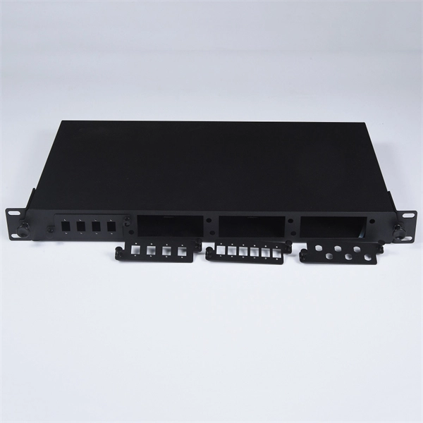
Sheath Bonding Link Boxes
Grounding link boxes are used at each end of every tri-section to bond the three cable sheaths to each other and to provide a low resistance ground connection. Cross bonding boxes are used at the two
Cross Bonding Link Box
Cross bonding link box is used for cross interconnection of high-voltage single-core cable metal sheath, limiting over voltage applied to cable sheath and both insulated part ends of insulated joint,
DESIGN MANUAL FOR HIGH VOLTAGE TRANSMISSION LINES
Current knowledge of the effects of high temperature operation on the long term behavior of conductors and associated hardware (splices, etc.) is probably limited; however, and a clear understanding of

JOINTING OF HIGH VOLTAGE CABLE SYSTEMS
This paper gives some technical background information about the design and the quality control of premoulded high voltage joints and highlights some aspects for an appropriate earthing concept of
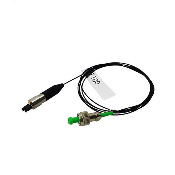
Optical Power Meters & Sources
High-precision power meters (Ge/InGaAs) and stabilized light sources for insertion loss and return loss testing.
OTDR & Fiber Characterization
Full-featured OTDR, fiber OTDR testers, and modular OTDR test modules for network deployment and troubleshooting.
OSA & Eye Diagram Analyzer
High-resolution OSA for DWDM and eye diagram testers for signal integrity validation.
BERT & Endface Inspection
BERT up to 800G, fiber endface inspection probes, and extinction ratio meters for comprehensive testing.