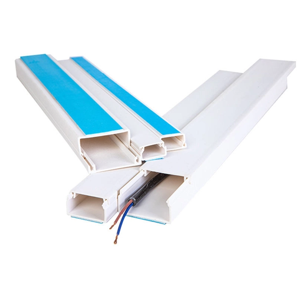
Complete cable tray manual for electrical engineers and designers
A small amount of engineering is required to change the width of a cable tray to gain additional wiring space capacity. Change is a complex problem when conduit banks are involved.
Translation
Google''s service, offered free of charge, instantly translates words, phrases, and web pages between English and over 100 other languages.
Best practice guide to cable ladder and cable tray
The following recommendations are intended to be a practical guide to ensure the safe and proper installation of cable ladder and cable tray systems
To Specify the Slope for Cable Tray
Slope is applied to cable tray in the Z direction of the current coordinate system in the drawing (typically the vertical direction for a building plan).

Quick Cable Tray Routing
The user can now create a cable tray run between the head and tail of the branch, using the mouse, the quick routing handles and the options available from the Model Editor.
CABLE TRAY SYSTEMS GUIDE
The Ladder Tray features light, rugged, tubular steel construction. It is designed for mechanical support and strain relief in long runs of cable and creates a smooth gradual bend for cable. Rail and stringer

B-Line series Cable Tray Design Considerations
Our wind certification report provides you with list of acceptable B-Line series cable tray supports, fittings and covers based off of the environmental conditions, cable loading, and type of cable tray in your
Beama Best Practice Guide | Installation Of The System | Cable
Cable ladders and cable trays should be mounted far enough off the floor or roof to allow the cables to exit through the bottom of the cable ladder or cable tray.
Cable Tray Technical Guide A practical guide to product selection
Cable tray length is selected based on the load to be supported, the distance between the supports (also referred to as the span), and handling and installation constraints.
Method Statement installation of Cable Trays and Ladders
This method statement covers the site installation of the cable tray & ladders and the requirements of checks to be carried out.
Slope Cable Tray Support
Slope Cable Tray Support - GA Drawing - Free download as PDF File (.pdf) or view presentation slides online.
Best Practice Guide to Cable Ladder and Cable Tray Systems
This guide covers cable ladder systems, cable tray systems, channel support systems and associated supports intended for the support and accommodation of cables and possibly other electrical
How to create slope Cable tray?
To do this, you might need to generate the geometry in Dynamo, rather than using system families based on curves. In this example, I have created a cable tray as a DirectShape (similar to an
Optical Power Meters & Sources
High-precision power meters (Ge/InGaAs) and stabilized light sources for insertion loss and return loss testing.
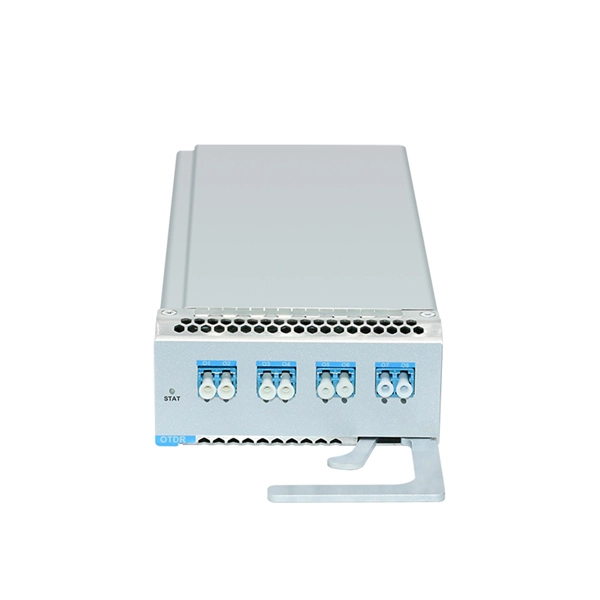
OTDR & Fiber Characterization
Full-featured OTDR, fiber OTDR testers, and modular OTDR test modules for network deployment and troubleshooting.
OSA & Eye Diagram Analyzer
High-resolution OSA for DWDM and eye diagram testers for signal integrity validation.
BERT & Endface Inspection
BERT up to 800G, fiber endface inspection probes, and extinction ratio meters for comprehensive testing.