Cisco Switch Layer2 Layer3 Design and Configuration
One simple and popular switch design scenario will be shown in the following tutorial. This scenario will fit most SMB networks (or even bigger ones) that have a few layer 2 VLANs and consequently a few

How to Connect Multiple Ethernet Switches Using Fiber Optic Cables
Most importantly, any upgrades and advancements in networking technology can be easily accommodated by existing fiber infrastructure, offering scalability for future network

Fiber Optic Ring Network Design Explained: Topologies, Diagrams
Learn how to design a fiber optic ring network with practical diagrams, topologies, and switch setup tips. Explore ring network switch options for industrial applications.
Connecting Network Switches via Fiber
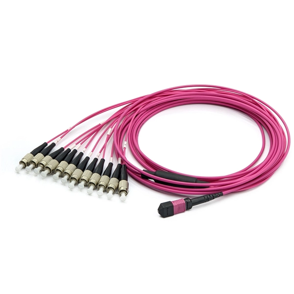
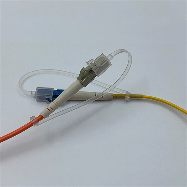
Always integrate duplex (two strand) fiber optic cabling or higher strand counts. Most modern SFP transceiver modules feature duplex LC connections. Terminate your fiber optic cabling with two LC
Application Guide: Connecting Fiber-ready Network Switches
Most modern fiber-enabled network switches require an SFP transceiver module featuring a duplex (two strand) multimode OM3 or duplex single mode OS2 connection with LC connectors. Direct attach

Scalance XC-206 2SFP Installation Instructions
The fiber switch has six RJ-45 ports (P1-P6) for Ethernet connections and two pair of fiber optic connection ports (P7-P8). Each fiber switch must be programmed with a unique IP address.
Network Diagram for Fiber Optics
Learn how fiber optic networks distribute data from central offices to end users. This diagram highlights media converters, switches, and cable types.
Understanding the fiber optic network diagram and its relation with
Fiber optic network diagrams represent the architecture and connectivity of fiber optic systems, and their design philosophy integrates technical, functional, and conceptual aspects. The
Fiber connection between 2 switches in 2 seperate buildings
In building A, the internet comes in trough a ISP cable modem, goes trough a PFSense firewall and a switch, before connecting internally to all of our devices. The problem I''m having is the

Fiber Optic Logical Network Diagram | EdrawMax Templates
They depict the logical flow of data between devices in a network, including wireless communication links, structured cabling, and fiber optic backbone connections. This visualization
Optical Power Meters & Sources
High-precision power meters (Ge/InGaAs) and stabilized light sources for insertion loss and return loss testing.
OTDR & Fiber Characterization
Full-featured OTDR, fiber OTDR testers, and modular OTDR test modules for network deployment and troubleshooting.
OSA & Eye Diagram Analyzer
High-resolution OSA for DWDM and eye diagram testers for signal integrity validation.
BERT & Endface Inspection
BERT up to 800G, fiber endface inspection probes, and extinction ratio meters for comprehensive testing.