Permanent Link Testing of Multimode and Singlemode Fiber
This document describes how and where permanent link loss testing should be performed based on the specifics of the cabling system. A link loss equation is used to calculate acceptable attenuation
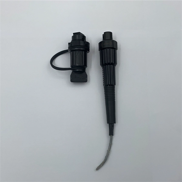
Duplex and multi-fiber OLTS
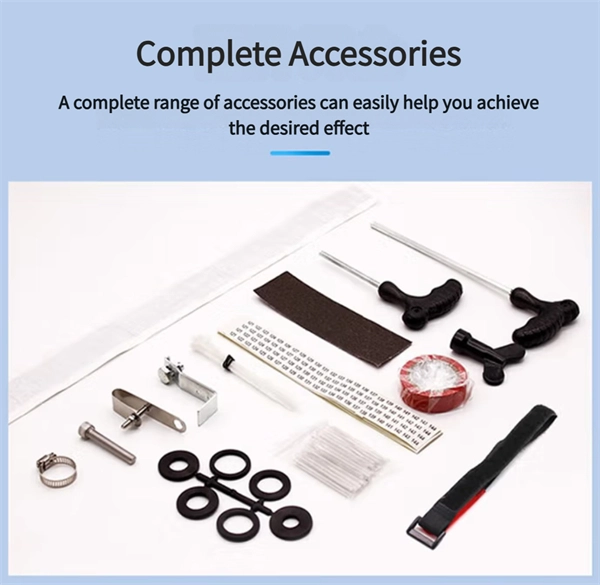
Tier-1 certification kit with power meter and light source, compatible with multiple duplex and multi-fiber connectors up to 24 fibers. Measures loss, length, and polarity in just 1 second, as per certification
Fiber Testing Standards 2025 Guide for IEC and TIA Compliance
The one-jumper method (Method B) is the industry standard for loss measurement. Use calibrated power meters and light sources. Record all results and update your practices as standards
Fiber Optic Testing Standards
No specific vendor is required for the Power Meter and Laser Light Source, but it must be able to operate at both 1310nm and 1550nm wavelengths. Both units must have a dynamic range suitable
Guidelines On What Loss To Expect When Testing
To be able to judge whether a fiber optic cable plant is good, one does a insertion loss test with a light source and power meter and compares that to an estimate of
OPTICAL FIBER POWER MEASUREMENTS
NIST maintains a set of calibrated transfer power meters that are available for a Measurement Assurance Program (MAP) comparison of optical fiber power meters. These transfer standards are
Fiber Optic Power Meter for Multimode and Singlemode Cabling
These units are ideal for measurement of optical power and optical loss/attenuations in a fiber optic network. The FOM120 meter is calibrated at the four most common industry standard wavelengths
Fiber Optic Cabling Loss Limits Explained – Trend Networks
Learn about fiber optic cabling loss limits & how to calculate them. Gain insights from experts on acceptable loss for cabling projects & explore the standards.
Guidelines On What Loss To Expect When Testing Fiber Optic Cables
To be able to judge whether a fiber optic cable plant is good, one does a insertion loss test with a light source and power meter and compares that to an estimate of what is a reasonable loss for that cable
Patchcord and Cable loss FOA-2a
This test will measure the loss of a fiber optic cable, singlemode or multimode, including connectors on each end individually. For short cables, e.g. patchcords, with negligible fiber loss, the measured loss
Guidelines Corning Recommended Fiber Optic Test
Corning Optical Communications reserves the right to improve, enhance, and modify the features and specifications of Corning Optical Communications products without prior notification.
TIA-526-14
This procedure can be used to measure the optical loss between any two passively-connected points, including end terminations, of a multimode optical fiber cable plant.
Optical Power Meters & Sources
High-precision power meters (Ge/InGaAs) and stabilized light sources for insertion loss and return loss testing.
OTDR & Fiber Characterization
Full-featured OTDR, fiber OTDR testers, and modular OTDR test modules for network deployment and troubleshooting.
OSA & Eye Diagram Analyzer
High-resolution OSA for DWDM and eye diagram testers for signal integrity validation.
BERT & Endface Inspection
BERT up to 800G, fiber endface inspection probes, and extinction ratio meters for comprehensive testing.