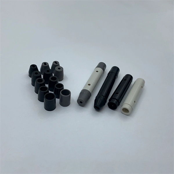
The Working Principle of the Fiber V-groove Array
Put the uncoated bare part of the fiber in the v groove. In this process, the fiber core is precisely positioned in the v groove by ultra-precision machining technology, to reduce the connection loss.
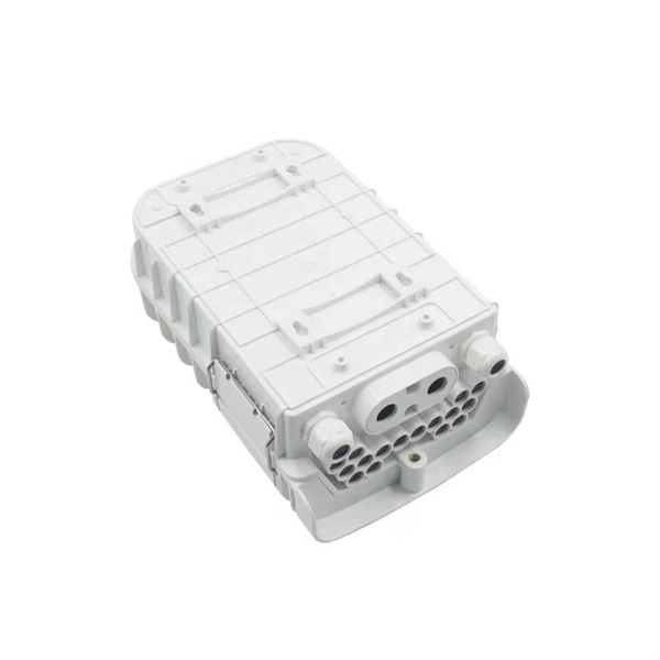
Fiber Couplers and Connectors
In any fiber optic communication system, in order to increase fiber length there is need to joint the length of fiber. The interconnection of fiber causes some loss of optical power.
Passive Alignment of Optical Fibers in V-grooves with Low
During the passive alignment process, the optical fiber may be lifted up by the buoyancy of epoxy flow and, hence, an extra cover plate is required to press the fiber against the walls of the V-groove. An
Methods of forming a v-groove for a fiber optics cable on an integrated
One illustrative device disclosed herein includes a V-groove in a base semiconductor layer of a semiconductor-on-insulator (SOI) substrate, wherein the V-groove is adapted to have a fiber...
V-Groove Substrates: Precise Positioning of Fiber Arrays
Multiple grooves are cut into the substrate, where the exposed parts of the optical fibers are precisely placed into the V-grooves. Using a pressurizer component to apply pressure and an adhesive to fix
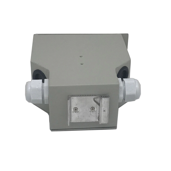
FIBER OPTIC CONSTRUCTION STANDARDS
Fiber optic cable sequential numbers are required at each pole location and vault wall. Sequential numbers will identify conduit length, and slack left in vaults and at poles.
V-Groove Fiber Array
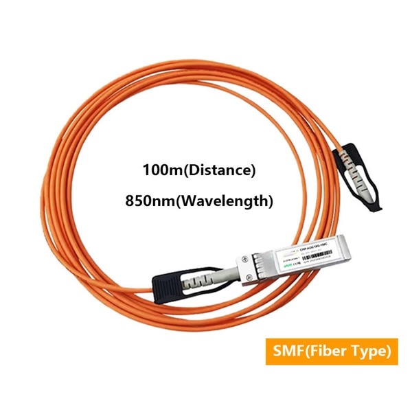
The connector cannot be installed directly onto bare fiber, as it is prone to damage during shipping. However, the connector can be assembled on bare fiber if a 3 cm protective loose tube is added for
DTS0083
The design of the V-Groove arrays offered by OZ Optics allows for up to 48 fibers to be connected at one time, maintaining the appropriate fiber spacing to achieve good light coupling, using either UV or
Fiber Alignment V-Groove: Precision For Optimal Fiber Optic
The Fiber Alignment V-Groove is a specially designed component used to align and hold optical fibers during the fusion splicing process. It typically consists of a precision machined metallic
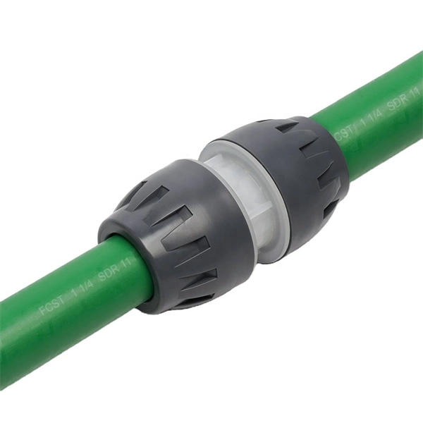
How to Splice Fiber Optic Cable – Step-by-Step Fusion Splicing Guide
Learn how to splice fiber optic cable using fusion splicing with this complete step-by-step guide. Includes tools, best practices, loss standards (ITU-T G.652), cost analysis, and FAQs for
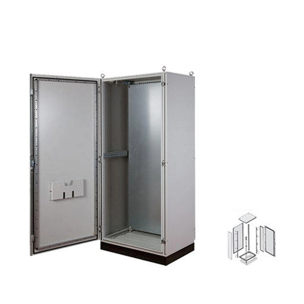
FOA Standard For Installing Fiber Optic Cable Plants
Installation is similar to installing a messenger wire except it also includes a fiber optic cable that requires careful handling like any other fiber optic cable.
Misalignment of the optical fibers in multi-channel V-grooves
The most important consideration for the reliability of multi-channel V-groove modules on silicon substrate is the misalignment of the optical fibers during the thermal loading. Failure of the
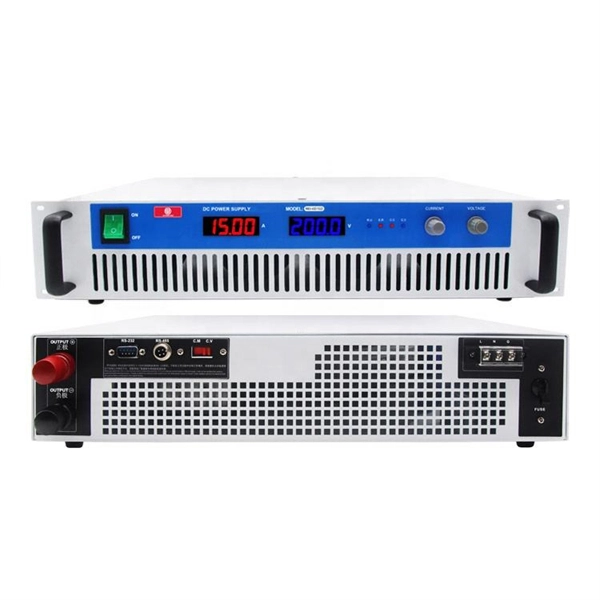
Optical Power Meters & Sources
High-precision power meters (Ge/InGaAs) and stabilized light sources for insertion loss and return loss testing.
OTDR & Fiber Characterization
Full-featured OTDR, fiber OTDR testers, and modular OTDR test modules for network deployment and troubleshooting.
OSA & Eye Diagram Analyzer
High-resolution OSA for DWDM and eye diagram testers for signal integrity validation.
BERT & Endface Inspection
BERT up to 800G, fiber endface inspection probes, and extinction ratio meters for comprehensive testing.