
Device physics. Schematic diagrams illustrating the
Schematic diagrams illustrating the working principles of the dual-mode OPD operated at a reverse bias (in the NIR light detection mode): (A) producing a
Technical note / Optics modules
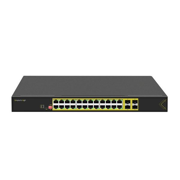
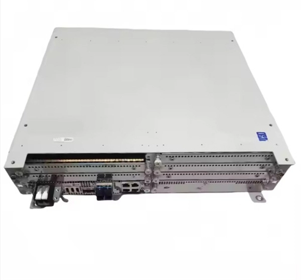
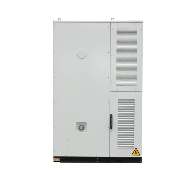
It has two sets of optical systems, each including a light source and a detector, so it is possible to measure two types of fluorescent reagents with one module.
Device physics. Schematic diagrams illustrating the working principles
Schematic diagrams illustrating the working principles of the dual-mode OPD operated at a reverse bias (in the NIR light detection mode): (A) producing a photocurrent in the presence...
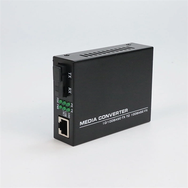
Optical Module Working Principle
Assuming that the output optical power remains unchanged, a decrease in the conversion slope will cause a decrease in the extinction ratio of the output optical signal, which will be reflected
Understanding Optical Modules: Working Principles,
The working principle of optical modules is illustrated in the diagram shown in the Optical Module Working Principle Diagram. The transmitting interface inputs
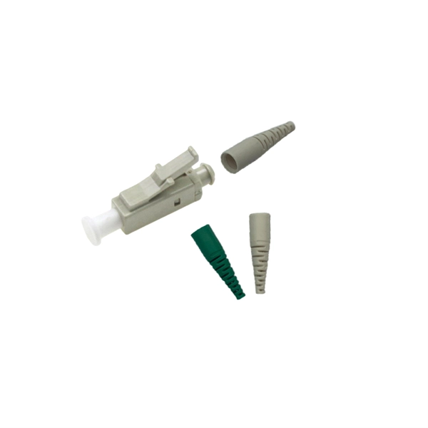
What are the Internal Components of an Optical Module?
The left side of the diagram shows a device that applies an optical module, such as a switch. The device inputs the signal to the optical module, which converts the electrical signal into
Understanding Optical Modules: Types and
Explore the essential principles and types of optical modules for fiber optic communication systems.
Understanding Optical Modules: Working Principles, Structures, and
The working principle of optical modules is illustrated in the diagram shown in the Optical Module Working Principle Diagram. The transmitting interface inputs electrical signals of a certain bit rate,
Microsoft PowerPoint
An optical interferometer is formed with the incoming light split, experiencing phase shifts through the two paths, and then recombined If the phase shift between the two waves is 0°, then there is
Optical module design resources | TI
View the TI Optical module block diagram, product recommendations, reference designs and start designing.
The Most Comprehensive Guide Of Optical Modules
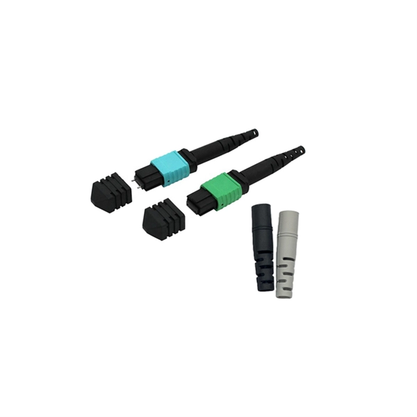
Its primary function is to achieve optoelectronic conversion by converting electrical signals into optical signals and vice versa.
Optical Module Working Principle | SFP Transceiver Technical Guide
Learn the complete working principle of optical modules (SFP transceivers), including TOSA/ROSA components, laser types, temperature compensation, and more. Weunion''s high
LM358 Dual Op-Amp Features, Pins, Working & Applications
The real image and pinout of the configuration of LM358 IC is shown in the diagram below which has eight pins in total having different individual functions associated with each of them.
Dual Beam CRO Block Diagram and Working Principle:
Dual Beam CRO Block Diagram and Working Principle: Figure 7.18 illustrates a block diagram of a Dual Beam CRO. The dual trace oscilloscope has one cathode ray gun, and an electronic switch which
Introduction To DML And EML Modulation Methods For
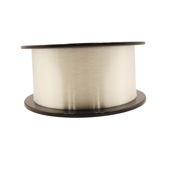
The optical signal transmitted through optical fibers is not constant; instead, it is a modulated signal with varying intensity. The characteristics and
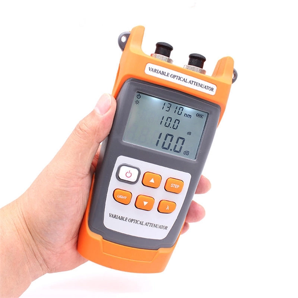
Optical Power Meters & Sources
High-precision power meters (Ge/InGaAs) and stabilized light sources for insertion loss and return loss testing.
OTDR & Fiber Characterization
Full-featured OTDR, fiber OTDR testers, and modular OTDR test modules for network deployment and troubleshooting.
OSA & Eye Diagram Analyzer
High-resolution OSA for DWDM and eye diagram testers for signal integrity validation.
BERT & Endface Inspection
BERT up to 800G, fiber endface inspection probes, and extinction ratio meters for comprehensive testing.