CABLE TRAY SYSTEMS GUIDE
Some applications may require the cable tray to support the weight of a single, dead object in addition to the cable loads. Specifications typically require this to be applied at the midpoint of the span between
A Guide to Installing and Supporting Electrical Cable Trays
This guide covers the critical steps, from selecting the right electrical cable tray and performing accurate cable fill calculations to managing a safe cable pull through and ensuring all bonding and grounding
Mounting instructions
Depending on the version, the fitting cover is mounted on the cable tray with turn buckles pre-mounted at the factory and is additionally held by the support of the path cover or held exclusively by the path
INSTALLATION GUIDE
Per NEMA V2, installing cover on outdoor cable tray systems is not common practice. Should they be required, proper attachment is required to protect them from the force of the wind.
GUIDE CABLE TRAYS TECHNICAL
If it has excellent electrical continuity and is integrated in the installation''s equipotential bonding system, a metal cable tray reduces the coupling''s impact and thus contributes to good EMC of the electrical
Cable Tray Technical Guide A practical guide to product selection
Cable tray length is selected based on the load to be supported, the distance between the supports (also referred to as the span), and handling and installation constraints.
CABLE TRAYS CONNECTION INSTRUCTIONS
determine the minimum size equipment grounding conductor needed to be installed within the entire cable tray system to be in compliance with the NEC. Note: Each cable tray section and fitting must
B-Line series Cable Tray Design Considerations
Our wind certification report provides you with list of acceptable B-Line series cable tray supports, fittings and covers based off of the environmental conditions, cable loading, and type of cable tray in your
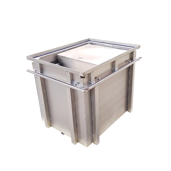
Cable Tray / Trough Tray INSTALLATION
) To install: place 1 part of cover clamp around trough tray cover and tray assembly. Place 2nd part around opposite end of Trough Tray, align clamp holes and install hardware.
Cable Tray / Ladder Tray INSTALLATION PowerTray
hoist ways or where subject to physical damage. Cable tray systems re to be installed so that they are accessible. If possible, leave 12” of space minimum free above and to the side of the tray
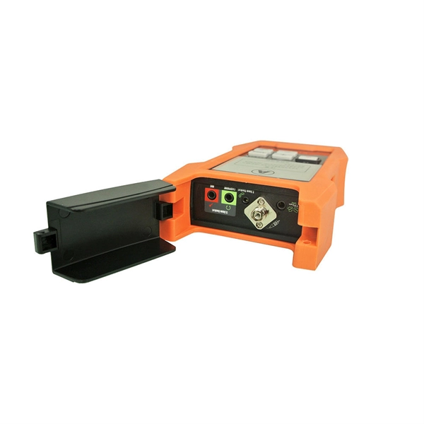
Optical Power Meters & Sources
High-precision power meters (Ge/InGaAs) and stabilized light sources for insertion loss and return loss testing.
OTDR & Fiber Characterization
Full-featured OTDR, fiber OTDR testers, and modular OTDR test modules for network deployment and troubleshooting.
OSA & Eye Diagram Analyzer
High-resolution OSA for DWDM and eye diagram testers for signal integrity validation.
BERT & Endface Inspection
BERT up to 800G, fiber endface inspection probes, and extinction ratio meters for comprehensive testing.