
Box Culvert Analysis and Design Presentation
Learn about box culvert analysis and design, including design criteria, loading conditions, and analysis methods. Civil engineering presentation.

1.12: Moment Distribution Method of Analysis of Structures
Draw the free-body diagram of each span of the given beam, showing the loads and moments at the joints obtained by the moment distribution method. Determine the support reactions
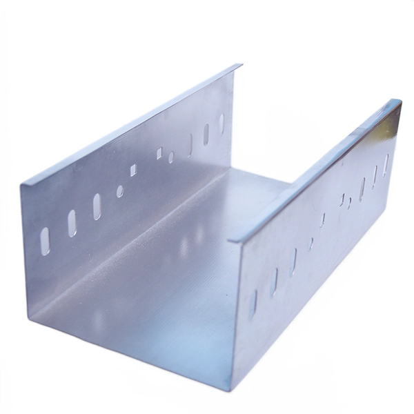
Bending (metalworking)
Bending is a manufacturing process that produces a V-shape, U-shape, or channel shape along a straight axis in ductile materials, most commonly sheet metal.

4: Bending
This page provides an overview of beams as structural elements, detailing their dimensions, attachment points, and analysis methods under bending loads using shear and moment diagrams.
Internal forces and moments: Jonathan Ochshorn''s Structural
Find the distribution of internal shear forces and bending moments for the beam shown in Figure 1.34, first by using FBDs and then by applying the rules from Appendix Table A-1.1.
Bending Mechanics: Comprehensive Guide to Material Deformation
In this article, we will discuss the fundamentals of bending, including bending moment, bending stress distribution, area moment of inertia, section modulus, bending in composite beams, bending stress

Ultimate Guide to Shear Force and Bending Moment Diagrams
Being able to draw shear force diagrams (SFD) and bending moment diagrams (BMD) is a critical skill for any student studying statics, mechanics of materials, or structural engineering.
Metal Bending 101: A Guide To Precision Sheet Bending
In this article, we will explore how metal bending works, review the main bending methods, discuss material considerations, highlight design tips, and provide guidance on selecting

Shear Force & Bending Moment Full Guide + Diagrams explained
Shear force & bending moment fully explained! Learn definitions, formulas, and calculations and diagrams step by step with clear examples.

Bending Fundamentals | Stress Analysis, Flexure & Strength
Explore the essentials of bending in engineering: stress analysis, flexure, material strength, and advanced bending concepts for robust designs.
How to Construct a Bending Moment Diagram for a
Learn how to create a bending moment diagram for a distributed load in engineering and structural analysis. Understand the concepts of bending moments, shearing
Design of Reinforced Concrete Beams per ACI 318-02
The actual distribution of the compressive stress in a section has the form of a rising parabola (Fig. 2a), and an equivalent rectangular stress block (Whitney block, Fig. 2b) can be used without loss of
Mechanics of Materials: Bending – Normal Stress
Bending results from a couple, or a bending moment M, that is applied. Just like torsion, in pure bending there is an axis within the material where the stress and strain are zero.

How to Construct a Bending Moment Diagram for a Distributed Load:
Learn how to create a bending moment diagram for a distributed load in engineering and structural analysis. Understand the concepts of bending moments, shearing forces, and distributed loads to

Bending: Definition, Process, and Types
Sheet metal bending is a metal forming process in which a flat sheet of metal is bent or folded to create a three-dimensional shape, angle, or curved, contoured angle change. Learn more

Bending: Meaning, Definition, Formulas, Stress, Stiffness, Strength
Learn everything about bending — meaning, definition, bending moment formula, stress, stiffness, strength, and uses in engineering and manufacturing industries.

Moment Distribution Method in Structural Analysis | PDF | Bending
Examples are provided to demonstrate how to set up and solve the moment distribution method by hand, including determining distribution factors, fixed-end moments, iterating to find internal member
Statics: Integration Method
In Section 8.5 we saw that loading, shear and bending moments are related by integral and differential equations, and in Subsection 8.7.2 used this knowledge to draw shear and bending moment diagram
Bending
In applied mechanics, bending (also known as flexure) characterizes the behavior of a slender structural element subjected to an external load applied perpendicularly to a longitudinal axis of the element.

Normal, Shear, and Bending Moment Diagrams: A Step By Step
The internal force distribution of a member will be determined using normal, shear, and bending moment diagrams.
Bending arts | Avatar Wiki | Fandom
Bending is the ability to manipulate an element and is significant to many aspects of life in the world. There are five known bending arts; four of them bend a specific physical element while the fifth bends

I-Line® Circuit Breaker Power Distribution Panelboards
To properly mount and install the I-Line panelboard enclosure, please refer to the NEMA PB 1.1-2007 standards publication, and follow the instructions below for either “Surface Mounting (Enclosure
Bending Moment Diagrams for Frames
This diagram helps visualize the variation of the bending moment along the member, enabling engineers to identify critical sections where the moment is highest and assess the potential

Understanding Shear Force and Bending Moment
This page will walk you through what shear forces and bending moments are, why they are useful, the procedure for drawing the diagrams and
Optical Power Meters & Sources
High-precision power meters (Ge/InGaAs) and stabilized light sources for insertion loss and return loss testing.
OTDR & Fiber Characterization
Full-featured OTDR, fiber OTDR testers, and modular OTDR test modules for network deployment and troubleshooting.
OSA & Eye Diagram Analyzer
High-resolution OSA for DWDM and eye diagram testers for signal integrity validation.
BERT & Endface Inspection
BERT up to 800G, fiber endface inspection probes, and extinction ratio meters for comprehensive testing.