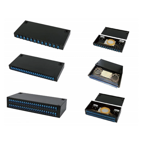
FOA Standard For Installing Fiber Optic Cable Plants
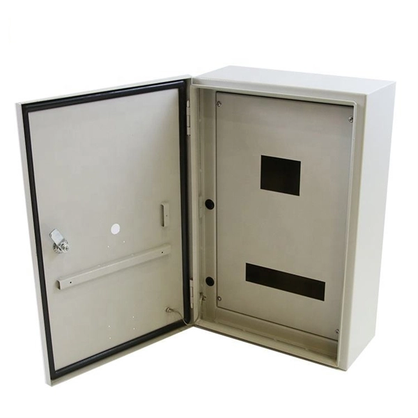
For non-rated OSP cables, the entrance facility should provide termination facilities for the OSP cable to connect to properly rated premises cables or transition to rated conduit to allow OSP cables to
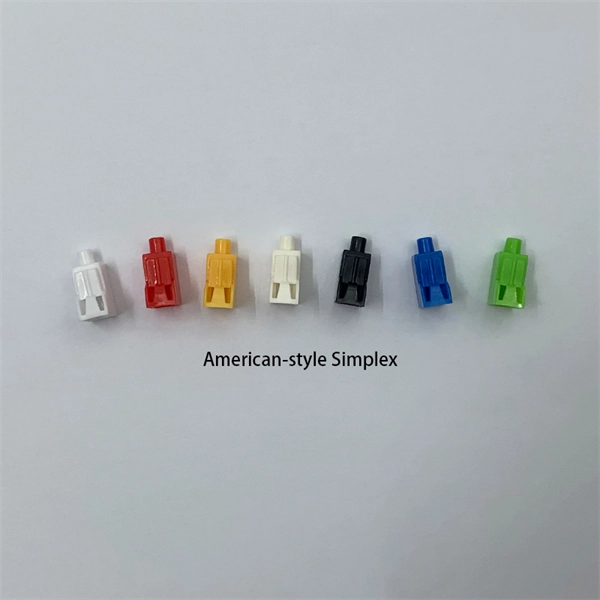
SuperNine® Tight-Tolerance MIL-DTL-38999 Sr. III Fiber Optic Connection
The high-performance MIL-DTL-38999 type fiber optic interconnect system with qualified MIL-PRF-29504/4 and /5 termini, successfully deployed in hundreds of commercial and military aerospace and
Handbook on OFC Jointing Techniques | PDF | Optical Fiber
The document provides information on optical fibre cable jointing. It discusses the construction of optical fibre cables which typically contain multiple glass or plastic fibres encased in a protective plastic jacket.
WORKMANSHIP STANDARD FOR FIBER OPTIC
12.2.1 Fiber optic cable assemblies should not be combined in the same wiring bundle as wire or coaxial cable assemblies to ensure they are not exposed to handling practices that are acceptable for
Joining Fiber Cable – What Are the Options?
Consequently, cables have to be connected or cut in the field, with the potential issues this entails. This blog post looks at the various options available to installers for responding to these issues; from
AC 43.13-1B
Title 14 of the Code of Federal Regulations part 43, section 43.13(a) states that each person performing maintenance, alteration, or preventive maintenance on an aircraft, engine, propeller, or appliance
Workmanship Standard for Fiber Optic Terminations, Cable
This Standard prescribes NASA''s process and end-item requirements for reliable fiber optic terminations, cables, assemblies, and the installation thereof. This NASA-STD was developed by
Tutorial Passive Fiber Optics, Part 6: Fiber Joints
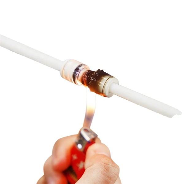
Another technique is fusion splicing, where the fibers are fused together, e.g. using an electrical arc. This leads to particularly low insertion loss and high return loss, if the two fiber cores are similar. For
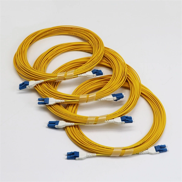
(PDF) Handbook on OFC jointing
It details various connector types, their specifications such as insertion loss and
OPTICAL FIBRE CABLE JOINTING
This handbook not only covers the information on optical fibre cable jointing but also have Reasons of Light Losses, Tools & Instruments, Troubleshooting, Maintenance Schedule, Safety Precautions and
ITU-T Rec. L.12 (05/2000) Optical fibre joints
At present two technologies, fusion and mechanical, can be used for splicing glass optical fibres and the choice between them depends upon the expected functional performance and considerations of
(PDF) Handbook on OFC jointing
It details various connector types, their specifications such as insertion loss and return loss, and best practices for handling and maintenance. The aim is to enhance the reliability and performance of
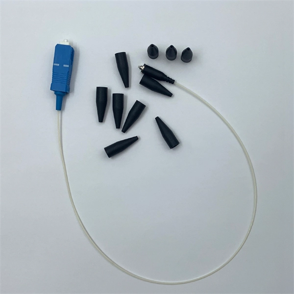
Fiber Optic Splicing and Termination
Fiber optic joints or terminations are made two ways: 1) splices which create a permanent joint between the two fibers or 2) connectors that mate two fibers to create a temporary joint and/or connect the
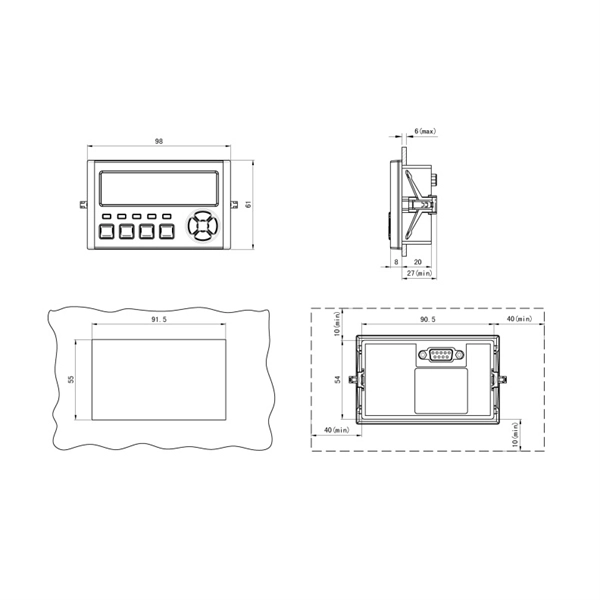
Optical Power Meters & Sources
High-precision power meters (Ge/InGaAs) and stabilized light sources for insertion loss and return loss testing.
OTDR & Fiber Characterization
Full-featured OTDR, fiber OTDR testers, and modular OTDR test modules for network deployment and troubleshooting.
OSA & Eye Diagram Analyzer
High-resolution OSA for DWDM and eye diagram testers for signal integrity validation.
BERT & Endface Inspection
BERT up to 800G, fiber endface inspection probes, and extinction ratio meters for comprehensive testing.