Cable Tray | Design Master Software Docs
Starting Elevation: The starting elevation of the cable tray. The reference point for the starting elevation of the cable tray is set by the Vertical Alignment .
Cable tray manual
Where the cable type may be used, cable tray may be installed to support it except as per Section 392.12 which states that cable trays shall not be installed in hoistways or where subject to severe
SECTION 26 05 36 CABLE TRAYS FOR ELECTRICAL
Designer shall provide a 12” vertical working clearance above the cable tray with no continuous obstructions. In addition, a 12” space must be provided on either side for working access.
NEC Article 392: Cable Tray Systems
It provides rules for acceptable wiring methods that can be
Cable Tray / Ladder Tray INSTALLATION PowerTray
General Installation Guidelines: latest NEMA standards and local building codes. Trough tray field support and frequency depends on the weight and const ction (splice locations, e bow fittings, etc.)
Cable Tray Technical Guide A practical guide to product selection
Cable tray installed in a hazardous location must contain only those cables that are appropriate for this type of environment as defined in Chapter 5 of the NEC.
Elevation Change Kit -Black | Wire Mesh Trays | Cable Tray
These three qualities make the Cablofil Wiremesh Cable Tray system preferred by installers.
SECTION 260536
Show fabrication and installation details of cable tray, including plans, elevations, and sections of components and attachments to other construction elements.
Ladder Trays | Cable Tray and Reels | Wire and Cable Management
Refers to the approximate height of a cable tray used for specifying. Selecting a specific height will show cable trays with that height, as well as cable tray accessories compatible with that height.
NEC Article 392: Cable Tray Systems
It provides rules for acceptable wiring methods that can be installed in cable trays, including conditions for use. It addresses uses permitted and not permitted for cable trays.
CABLE TRAY SYSTEMS GUIDE
It is designed for mechanical support and strain relief in long runs of cable and creates a smooth gradual bend for cable. Rail and stringer material is 16 ga steel tubing.
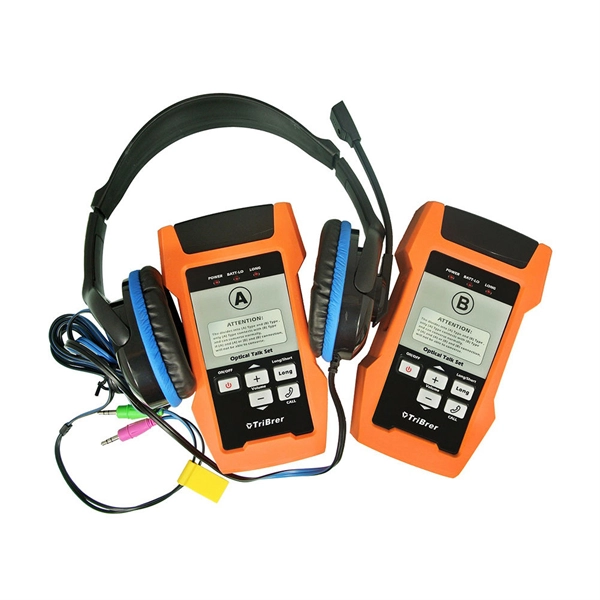
Optical Power Meters & Sources
High-precision power meters (Ge/InGaAs) and stabilized light sources for insertion loss and return loss testing.
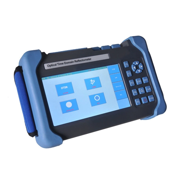
OTDR & Fiber Characterization
Full-featured OTDR, fiber OTDR testers, and modular OTDR test modules for network deployment and troubleshooting.
OSA & Eye Diagram Analyzer
High-resolution OSA for DWDM and eye diagram testers for signal integrity validation.
BERT & Endface Inspection
BERT up to 800G, fiber endface inspection probes, and extinction ratio meters for comprehensive testing.