E&I Electrical and Instrumentation
we deliver a comprehensive range of solutions, from fully integrated EPC to working on behalf of our Client. Over 560,000 Meters of Cable Pulling, and 3300 Pieces of Instruments, INJURY FREE, Over
Cable Tray Installation Procedure Guide
It describes inspecting and storing cable trays upon receipt, installing trays flat or vertically, fixing trays to structures, designing trays to carry loads, providing covers in areas with risk of damage, allowing
Method Statement installation of Cable Trays and Ladders
This method statement covers the site installation of the cable tray & ladders and the requirements of checks to be carried out.
METHOD STATEMENT FOR Cable tray and trunking system installation
The cable tray shall be installed with a 40mm minimum space between the structure and the tray. All cable shall be securely fixed to the tray, work and the complete installation must be carried out in a
Instrumentation Cable Tray Installation Checklist and
Step-by-step instrumentation cable tray installation guide with safety tips, standards, inspections, and downloadable Excel checklist.
Cable Tray Systems: Requirements and Best Practices
This article explains the main requirements and good practices for cable tray systems, including tray types, materials, loading, supports, bonding, cable selection, and installation details.

Cable Tray and Conduit Installation Method Statement
This method statement describes a detailed procedure for properly installing cable trays and conduits for the Feeder System.
Cable Tray Installation
Proper planning for installing cable tray includes calculations based on loading, support systems, cable/wire fill and spacing, conductor types, securing of the cables and wire, and proper grounding
METHOD STATEMENT FOR CABLE TRAY INSTALLATION
2.0 This method statement will cover the minimum requirements for installation of cable trays and other related electrical works to be applied at the site for commercial buildings, plants and refineries.
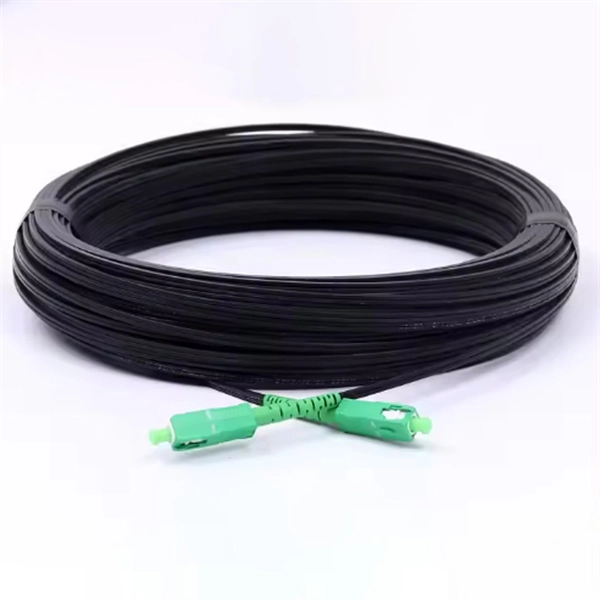
NYCO Group
Installation and connection of OPGW. Pulling (laying,Blowing), splicing of Fiber optic cables (FOC). Installation of telecommunication equipment. (PLC panels, MUX, coupling filters, coaxial cablesetc)
Optical Power Meters & Sources
High-precision power meters (Ge/InGaAs) and stabilized light sources for insertion loss and return loss testing.
OTDR & Fiber Characterization
Full-featured OTDR, fiber OTDR testers, and modular OTDR test modules for network deployment and troubleshooting.
OSA & Eye Diagram Analyzer
High-resolution OSA for DWDM and eye diagram testers for signal integrity validation.
BERT & Endface Inspection
BERT up to 800G, fiber endface inspection probes, and extinction ratio meters for comprehensive testing.