FEEDER PROTECTION CALCULATIONS & SETTINGS
Relay coordination is the process of selecting settings that will assure that the relays will operate in a reliable and selective way. In OC relays the coordination is based on the relay time-current
Relay Settings Calculations
To avoid relay mal-operation, set Slope 2 as high as possible. Normally, a high Slope 2 setting causes slow tripping for evolving faults (external-to-internal faults).
A Guide for Calculating Step Distance Relay Settings
For three-terminal lines where the remote station has no breaker-failure protection, set the relay to reach 110% of the sum of the protected line impedance with infeed and the remote line impedance with the
Distance Protection Relay Settings Guide
Setting calculations require information about line and transformer parameters, CT and PT ratios, and arc resistance to determine impedance-based protection zones and resistive reaches.
Protection Relay Settings Calculations Made Easy
In this post, you will find relay settings calculations that serve as a guide to developing your settings. Some important areas are as follows: Line protection among other sub-details.
Transmission Line Setting Calculations – Beyond the Cookbook
There are several approaches for making relay setting calculations. One approach is to calculate a setting and then do a number of checks to verify that the calculated setting is acceptable.
Relay Coordination Study: Selectivity Calculations | EEP
The scope of study involves calculating the settings for protective relays to achieve selectivity during faults ocurring in the electrical network for the 13.8 kV and 4.16 kV projects.
Protection Relay Setting Interactive Calculator | FIRGELLI
Use this Protection Relay Setting Calculator to calculate pickup current, time multiplier settings (TMS), operating time, coordination time interval (CTI), and plug setting multiplier (PSM)
Generation Protection Calculations and Settings
• A time delay setting of 1 cycle is optimal from a protection standpoint, but ensure it is secure for external faults, which is primarily dependent upon CT saturation performance matching i.e., CT

Relay Protection in HV/MV Substations: Calculations, Settings
This comprehensive article delves into the key aspects of relay protection in HV/MV substations, including calculations, settings, coordination, selection, and validation, which are all...
Optical Power Meters & Sources
High-precision power meters (Ge/InGaAs) and stabilized light sources for insertion loss and return loss testing.
OTDR & Fiber Characterization
Full-featured OTDR, fiber OTDR testers, and modular OTDR test modules for network deployment and troubleshooting.
OSA & Eye Diagram Analyzer
High-resolution OSA for DWDM and eye diagram testers for signal integrity validation.
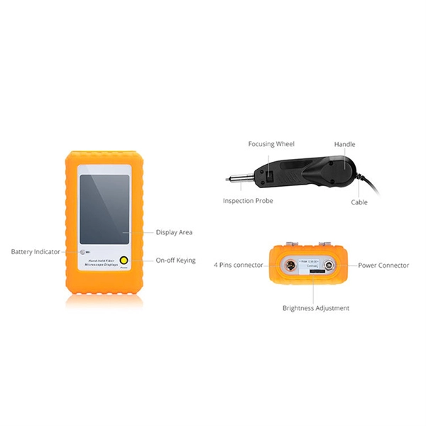
BERT & Endface Inspection
BERT up to 800G, fiber endface inspection probes, and extinction ratio meters for comprehensive testing.