37W_17249_6_Fundamentals_of_Real-Time_Spectrum_Analysis
This section contains several architectural diagrams of the main acquisition and analysis blocks typical of Tektronix RTSAs. Specific implementations vary by model number and by specific measurement
Real-Time Spectrum Analyzer Fundamentals
The RSA''s RF/IF block diagram demonstrates its signal conditioning process, which includes variable attenuation, multi-stage frequency conversion, and analog filtering.

Agilent Spectrum Analysis Basics
Figure 7 is a simplified block diagram of a super-heterodyne spectrum analyzer. Heterodyne means to mix - that is, to translate frequency - and super refers to super-audio frequencies, or frequencies
The schematic diagram of the designed direct-reading linear
The schematic diagram of the designed direct-reading linear polarization analyzer and cascaded meta-atoms. (a) The perspective view of the model. (b) The configuration of the cascaded...
Spectrum Analyzer Basics for RF Engineers
Learn the fundamentals of spectrum analyzers, including block diagrams, key settings, and measurement techniques for RF signal analysis.
SPECTRUM ANALYZER
Fig. 7 Block diagram of an audio spectrum analyzer. Such analyzers are usually restricted to audio-frequency applications and may employ as many as 32 filters. The bandwidth of each filter is
11410-00796B Guide to Spectrum and Signal Analysis AN dd
Spectrum analyzers are the most versatile tools available to the RF engineer. This guide will describe the critical performance characteristics of spectrum and signal analyzers, the types of signals
1MA201_09e
Fig. 4: Block diagram of an FFT analyzer. In practice, the Fourier transform is performed with the aid of digital signal processing (discrete Fourier transform), which means that the signal to be analyzed
SPECTRUM ANALYZER FUNDAMENTALS
the signal isn''t a sine wave?" Well, many years ago—and you''ll have to take this on faith or learn Fourier analysis—it was discovered that a signal can be represented as a sum of simple sine waves.
Spectrum Analysis Basics
At the most basic level, a spectrum analyzer can be described as a frequency-selective, peak-responding voltmeter calibrated to display the rms value of a sine wave. It is important to understand
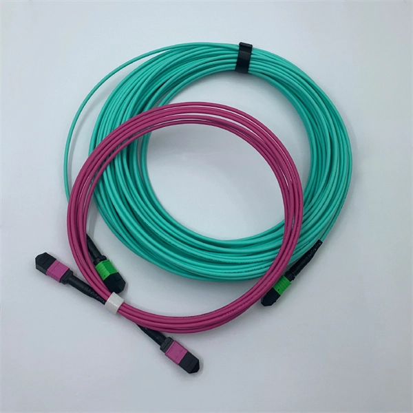
Optical Power Meters & Sources
High-precision power meters (Ge/InGaAs) and stabilized light sources for insertion loss and return loss testing.
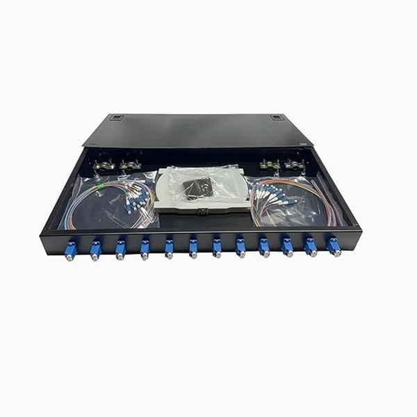
OTDR & Fiber Characterization
Full-featured OTDR, fiber OTDR testers, and modular OTDR test modules for network deployment and troubleshooting.
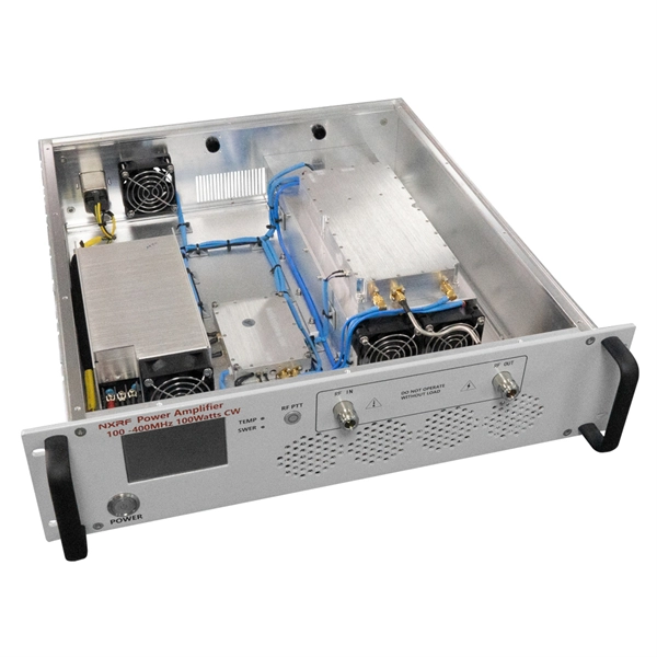
OSA & Eye Diagram Analyzer
High-resolution OSA for DWDM and eye diagram testers for signal integrity validation.
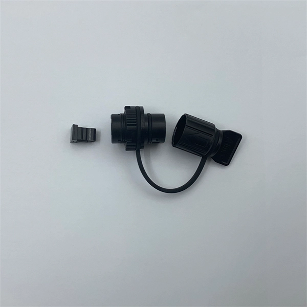
BERT & Endface Inspection
BERT up to 800G, fiber endface inspection probes, and extinction ratio meters for comprehensive testing.