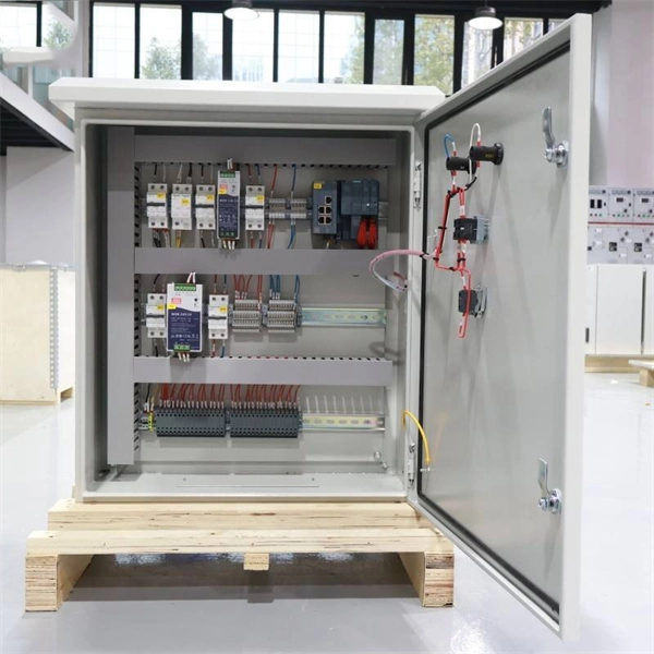
SCHEMATIC REPRESENTATION OF POWER SYSTEM
Prepared by Working Group I5 Working Group Assignment presentation of protection and control relaying. The report will identify methodology behind these practices, present issues
Distance Relay Protection Zones Explained
Distance protection measures the impedance of a circuit to detect faults by comparing voltage and current. It provides directional fault detection using a mho characteristic on an R-X diagram.

Distance Protection Working Principle & Fault Location Detection
Prepared by Working Group I5 Working Group Assignment presentation of protection and control relaying. The report will identify methodology behind these practices, present issues
Static Distance Protection Relay
The combinations of relays shown in Figs. (12.21) and (12.22) may be repeated for each phase of the protected circuit for earth-fault protection, and a separate group of relays may be used for phased
Circuit Diagram Of Distance Relay
A distance relay circuit diagram is a simplified representation of the different components in a distance relay and how they interact. The diagram typically consists of a power source, the relay
Distance Protection Working Principle & Fault Location Detection
These relays are called as distance protection relays. The relay operation is purely depending upon the magnitude of the circuit current and voltage, typically the ratio of the circuit to be protected is calculated.

Distance Relay: Types, Diagrams, and Working Principles
A diagram of a distance relay describes how the working of the relay is based on the impedance measurement within a power system. The general layout shows the relay unit, voltage
Distance (21) Protection | Electric Power Measurement and Control
The following photograph shows a pair of Westinghouse electromechanical distance relays mounted next to a pair of time-delay units, each timer providing a different amount of delay for each of the two
The schematic diagram of distance protection
In this research work, an adaptive scheme for the coordinated protection of AC Microgrids using directional overcurrent (DOCR) relays is presented.
Principles and Characteristics of Distance Protection
SIPROTEC 7SA522 protection relay – Single line diagram (provides full-scheme distance protection and incorporates all functions usually required for the protection of a power line)
Distance Protection
Such protection relays are known as “distance protection relays” and only function in case of faults that occur between the location of the protection relay and the chosen reach point.
Optical Power Meters & Sources
High-precision power meters (Ge/InGaAs) and stabilized light sources for insertion loss and return loss testing.
OTDR & Fiber Characterization
Full-featured OTDR, fiber OTDR testers, and modular OTDR test modules for network deployment and troubleshooting.
OSA & Eye Diagram Analyzer
High-resolution OSA for DWDM and eye diagram testers for signal integrity validation.
BERT & Endface Inspection
BERT up to 800G, fiber endface inspection probes, and extinction ratio meters for comprehensive testing.