9 Recommended Practices for Grounding
Use equipment grounding conductors sized equal to the phase conductors to decrease circuit impedance and improve the clearing time of overcurrent protective devices. Bond all metal
Industrial Electrical Grounding Requirements Guide
Our Industrial Electrical Construction team brings decades of experience designing and installing grounding systems that meet these rigorous requirements, ensuring your facility operates safely and
eTool : Construction
Conductors used for grounding fixed or moveable equipment, including bonding conductors for assuring electrical continuity, must be able to safely carry any fault current that may be imposed on them.
Grounding Practices in Power Distribution Systems
The installation of grounding methods for transmission lines is absolutely necessary in order to guarantee the safety, dependability, and effectiveness of power distribution systems.
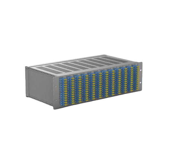
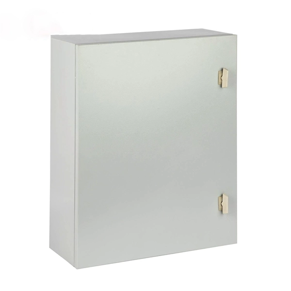
The installation requirements for the distribution box
Learn how to install a distribution box safely and correctly. Covers wiring, placement, standards, and expert tips for a compliant setup.
Grounding of commercial and industrial power systems
A properly designed and well-maintained grounding system significantly reduces the chance of personnel electrocution, electrical fires, equipment damage and associated downtime.
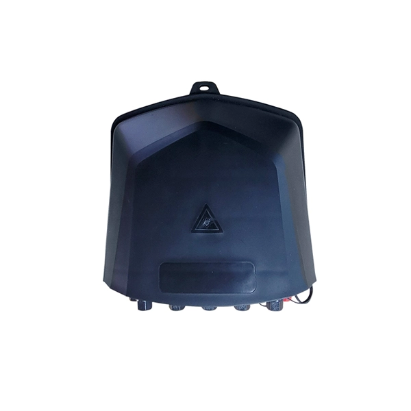
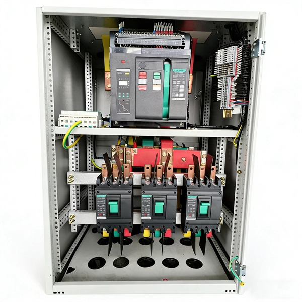
Correct Connection Method Of Grounding Wire Of
Open the distribution box and find the position marked with the grounding plate or PE letter. This position is the connection point of the grounding
The Basics of Grounding and Bonding
These tables help you properly size wiring for the grounding and bonding of your electrical system. Becoming familiar with the proper use of these tables can help installers ensure proper grounding
Grounding system construction: key points for grounding distribution
That''s why today we''ll break down the life-or-death details of grounding distribution boxes and cable shielding layers using plain language. No textbook fluff – just what actually works in the
Correct Connection Method Of Grounding Wire Of Distribution Box
Open the distribution box and find the position marked with the grounding plate or PE letter. This position is the connection point of the grounding wire in the box.

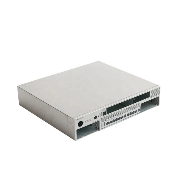
Transformer and Distribution Cabinet Equipment Installation
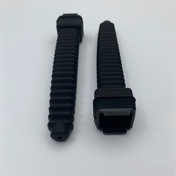
During insertion, the grounding contact should connect before the main contact; during withdrawal, the grounding contact should disconnect after the main contact.
9 Recommended Practices for Grounding
During insertion, the grounding contact should connect before the main contact; during withdrawal, the grounding contact should disconnect after
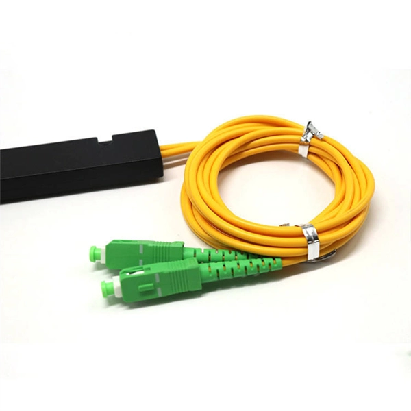
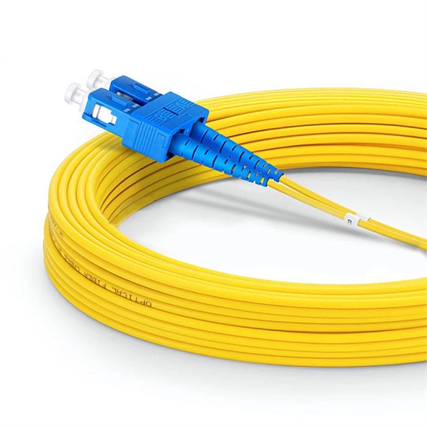
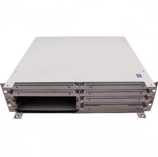
Optical Power Meters & Sources
High-precision power meters (Ge/InGaAs) and stabilized light sources for insertion loss and return loss testing.
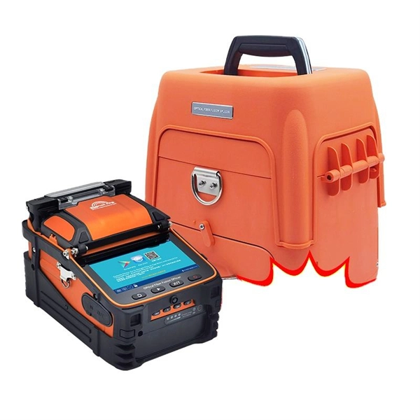
OTDR & Fiber Characterization
Full-featured OTDR, fiber OTDR testers, and modular OTDR test modules for network deployment and troubleshooting.
OSA & Eye Diagram Analyzer
High-resolution OSA for DWDM and eye diagram testers for signal integrity validation.
BERT & Endface Inspection
BERT up to 800G, fiber endface inspection probes, and extinction ratio meters for comprehensive testing.