Best Practice Guide to Cable Ladder and Cable Tray Systems
These rollers should be properly spaced dependent on the size and weight of the cable to prevent the cable from sagging and dragging in the cable tray or cable ladder during the pull.
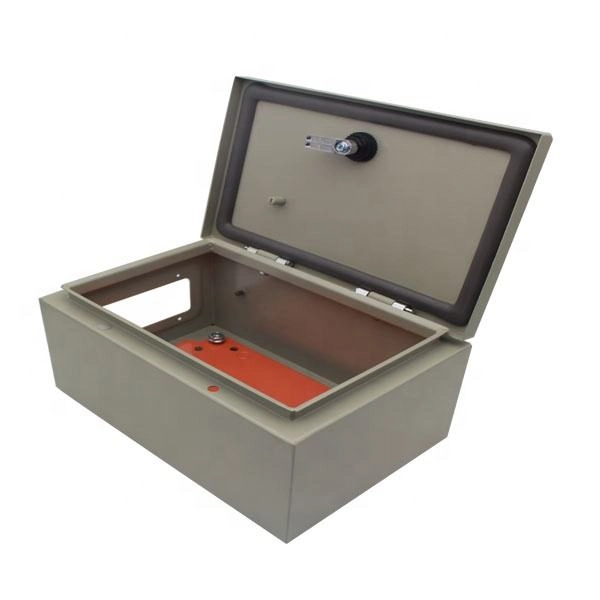
Full cable tray systems specification document
A. Test cable trays to ensure electrical continuity of bonding and grounding connections, and to demonstrate compliance with specified maximum grounding resistance.

Cable Tray Installation Rules (NEC 392) – Electrical Trader
Fill Limits: For power cables, the fill must not exceed 40% of the tray''s cross-sectional area; for control cables, it''s 50%. Separation: High-power and low-power cables must be separated
Explaining NEC Article 392 on Cable Trays
For non-horizontal runs, cables should be fastened securely to transverse members of the cable tray. Supports must be provided to prevent stress on cables where they enter raceways from
NEC Article 392 Guide: Ensuring Compliance for Cable Tray Systems
Strong hangers or brackets should be used to ensure that cable trays do not fall or hang. According to the regulations under NEC 392.30, these supports have to be put at a consistent
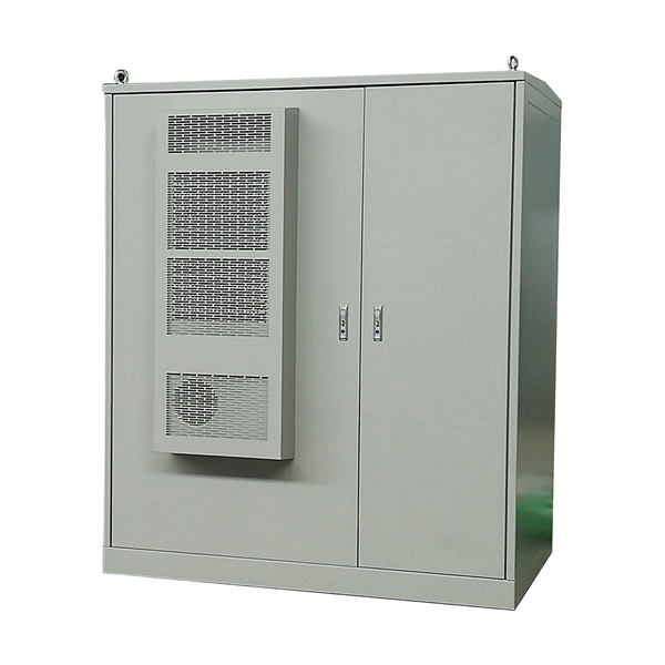
5 Golden Rules for Safe & Compliant Cable Tray Installation
Ensure safety and compliance in your cable tray installation. Discover the 5 golden rules covering NEC standards, load capacity, grounding, and support spacing.
Cable Tray Installation Guidelines for Engineers
Cable tray elbows shall be supported per NEMA VE 2 requirements. Cable tray supports shall be located so that connectors between horizontal straight sections of tray fall between the support point
NEC Questions and Answers based on 2017 NEC ®
Cable trays must be installed as a complete system, except mechanically discontinuous segments between cable tray runs, or between cable tray runs and equipment are permitted.
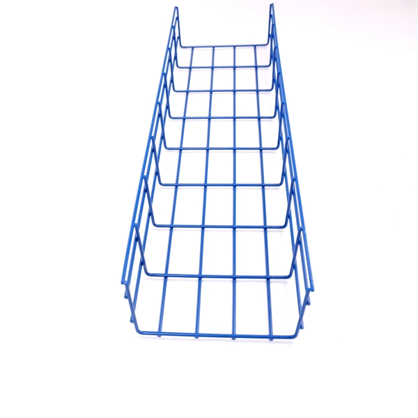
Cable Installation Guidelines in Trays | PDF | Cable | Rope
The document provides guidelines for installing cable in cable trays, including design considerations and formulas for calculating maximum tensions, sidewall pressures, bending radii, and more.
A Guide to Installing and Supporting Electrical Cable Trays
This guide covers the critical steps, from selecting the right electrical cable tray and performing accurate cable fill calculations to managing a safe cable pull through and ensuring all bonding and grounding
Optical Power Meters & Sources
High-precision power meters (Ge/InGaAs) and stabilized light sources for insertion loss and return loss testing.
OTDR & Fiber Characterization
Full-featured OTDR, fiber OTDR testers, and modular OTDR test modules for network deployment and troubleshooting.
OSA & Eye Diagram Analyzer
High-resolution OSA for DWDM and eye diagram testers for signal integrity validation.
BERT & Endface Inspection
BERT up to 800G, fiber endface inspection probes, and extinction ratio meters for comprehensive testing.