SCHEMATIC REPRESENTATION OF POWER SYSTEM
Communication diagram [telecommunications, block diagram, local area network (LAN) architecture diagram] Telecommunications related diagrams detail operating requirements for the
AN-CM-318 DC Power Line Communication
This application note presents how to implement a low cost, low power, DC power line communication based on GreenPAK and capacitive coupling. Compared with other solutions, the main advantage of
Build better -48 VDC power for 5G and next generation
Figure 1 is a diagram of a typical telecommunication DC power supply system, highlighting how -48 VDC is created and distributed.

Power Supply in Telecommunications
2 Requirements of Telecommunications Systems on the Power Supply 2.1 D.C. Power Supplies 2.1.1 Level of the Direct Voltages 2.1.2 Tolerance for Direct Voltages 2.1.3 Purity of Direct Voltages

Architecture of the dc power bus communication system.
As shown in Fig. 1, a single power bus line originating with a dc power supply extends to a number of "nodes," or actuator and sensor units. Encoder readings,

Composition and frame diagram of the communication power supply system
For this reason, an optimized design of electronic communication systems is required. Fig. 1 shows the composition and frame diagram of the communication power supply
Building a Better –48 VDC Power Supply for 5G and
Figure 1 presents a simplified diagram of a typical telecommunications DC power system with an emphasis on how –48 V DC is created and distributed.

DC POWER SYSTEM DESIGN FOR TELECOMMUNICATIONS
3In general, most stand-alone uninterruptible power systems have a relatively short battery reserve time—typi-cally 15 min to 1 h—compared to the telecommunications dc power system.
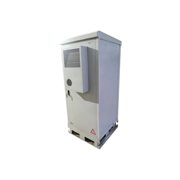
A Beginner''s Guide to Understanding Telecom Power
Understand telecom power supply systems, their components, and their role in ensuring uninterrupted communication and reliable network operations.

Composition and frame diagram of the communication
For this reason, an optimized design of electronic communication systems is required. Fig. 1 shows the composition and frame diagram of the communication
DC Power-System-Design-for-Telecommunications PDF
This is a book on the design of dc power systems that operate at nominal voltages of 24 and 48 V direct current (dc) and use lead–acid batteries and are used in public network
Communications System Power Supply Designs
These are three of the many telecommunication power supply applications that challenge power system designers to analyze a wide range of power distribution architectures and converter topologies.
Optical Power Meters & Sources
High-precision power meters (Ge/InGaAs) and stabilized light sources for insertion loss and return loss testing.
OTDR & Fiber Characterization
Full-featured OTDR, fiber OTDR testers, and modular OTDR test modules for network deployment and troubleshooting.
OSA & Eye Diagram Analyzer
High-resolution OSA for DWDM and eye diagram testers for signal integrity validation.
BERT & Endface Inspection
BERT up to 800G, fiber endface inspection probes, and extinction ratio meters for comprehensive testing.