Grounding System Installation Standards for Distribution Boxes and
Whether you''re a seasoned pro or just starting out, this comprehensive guide will give you practical insights into proper grounding techniques, with a special focus on how selecting quality materials
250.148 Continuity of Equipment Grounding Conductors and
Section 250.148 provides all of the methods permitted for ensuring proper continuity between the equipment grounding conductors when a box is installed, and circuit conductors are spliced within

NEC Requirements for Grounding of Services | EC&M
Correct grounding of services depends upon understanding the definition and role of the grounded conductor.
FESHM 9190: GROUNDING REQUIREMENTS FOR
Each enclosure receiving power from the electrical distribution system shall be bonded to the equipment grounding conductor in the cord or conduit supplying power to the enclosure.

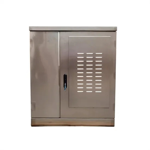
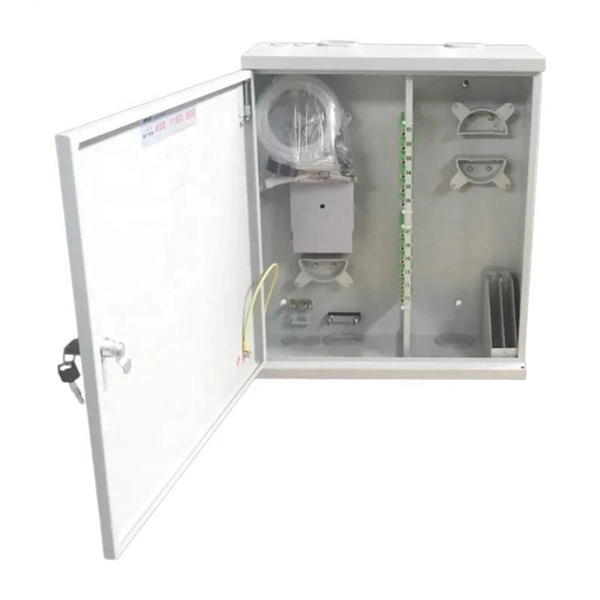
DISTRIBUTION BOX
Each DISTRIBUTION BOX and controller must be grounded. On the US market, a 5.26 mm 2 (10 AWG) ground wire must be used, and in all other markets a 6 mm 2 must be used.
ARTICLE 250 GROUNDING AND BONDING
Because the earth isn''t suitable to serve as the required effective ground-fault current path, an equipment grounding conductor is required to be installed with all circuits.

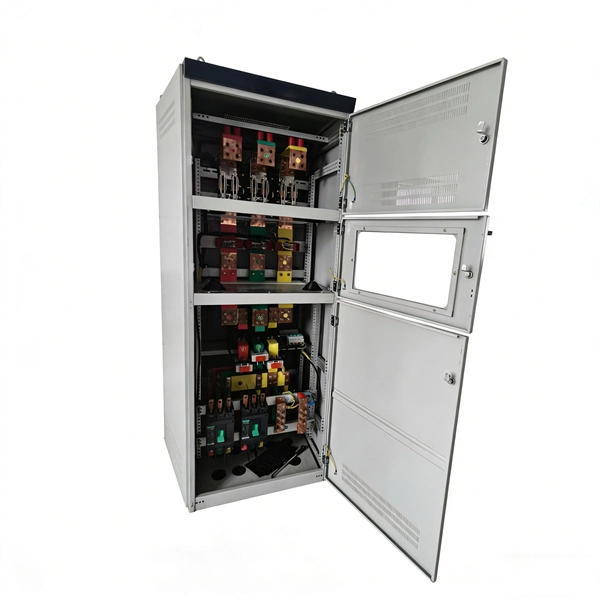
GROUNDING AND BONDING FOR ELECTRICAL SYSTEMS
The designer will evaluate the sizing of the grounding system and the need for an isolated or bonding ground system separate from the building grounding system.
26 05 26 GROUNDING AND BONDING FOR ELECTRICAL
3.11 Where metal covers on pull boxes and junction boxes are used, they shall comply with the grounding and bonding requirements of NEC Article 250.
Grounding Paper
Effective grounding, or earthing, of the distribution system neutral is necessary to achieve several objectives, the most important of which is the safety of the public and utility personnel.

Section 26 05 26, Grounding and Bonding for Electrical Systems
Ground resistance measurements shall be made before the electrical distribution system is energized or connected to the electric utility company ground system, and shall be made in normally dry
10-15-* Grounding with a meter base on the supply side of service
Where the consumer''s service has a single meter base and service box, the Ontario Electrical Safety Code (OESC) permits the grounding connection at the meter base or at the service box as per

Section 26 05 26 Grounding and Bonding for Electrical Systems
The A/E shall include details on the drawings, and edit details as necessary to comply with project scope and latest codes. This section specifies the furnishing, installation, connection, and testing of
Optical Power Meters & Sources
High-precision power meters (Ge/InGaAs) and stabilized light sources for insertion loss and return loss testing.
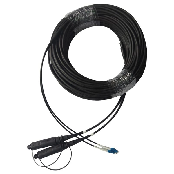
OTDR & Fiber Characterization
Full-featured OTDR, fiber OTDR testers, and modular OTDR test modules for network deployment and troubleshooting.
OSA & Eye Diagram Analyzer
High-resolution OSA for DWDM and eye diagram testers for signal integrity validation.
BERT & Endface Inspection
BERT up to 800G, fiber endface inspection probes, and extinction ratio meters for comprehensive testing.