FIBER OPTIC CONSTRUCTION STANDARDS
Fiber optic cable sequential numbers are required at each pole location and vault wall. Sequential numbers will identify conduit length, and slack left in vaults and at poles.
Master Your Fibre Optic Installation: Step-by-Step Best Practices
This comprehensive guide delves into the intricacies of fiber optic installation, exploring topics ranging from cable types and pre-installation considerations to execution, safety protocols,
OPTICAL FIBRE CABLES INSTALLATION GUIDE
In any cable deployment, whether it is optical fibre or any other type of cable, it should be considered the considerable number of tasks related to the manipulation and laying of the cable. Cable laying needs
Optical Fiber Communication Engineering Design Optical Fiber
To ensure the proper functioning of fiber-optic communi-cations, it''s crucial to identify the key features, technical requirements, and key issues to consider, and implement appropriate
Direct-Buried Installation of Fiber Optic Cable
Personnel feeding cable into a feed-chute must make sure that they do not position themselves inside a cable loop. Hearing protection may be required by vehicle operators. Pre-ripping provides a safety
Fiber Optic Cable Installation Method | PDF | Optical Fiber
Post-installation testing includes continuity and attenuation testing using an OTDR to ensure the cable is usable and identify any damage before termination. Cables are then terminated
FOA Standard For Installing Fiber Optic Cable Plants
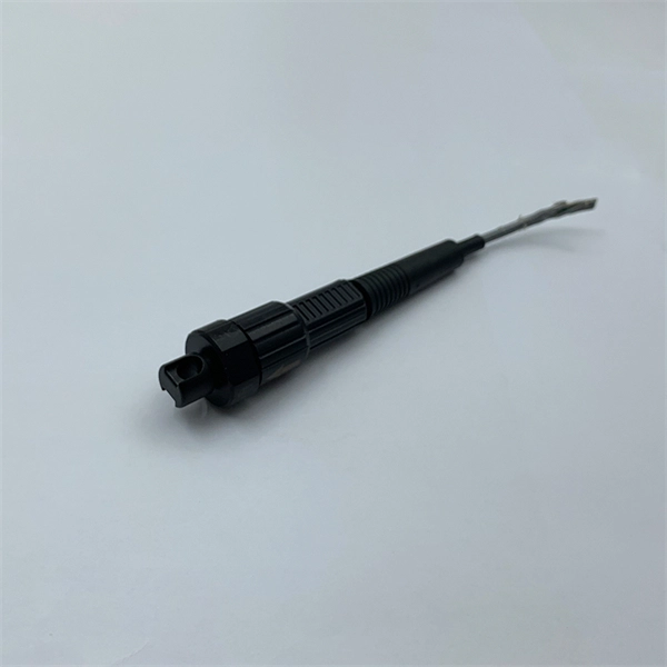
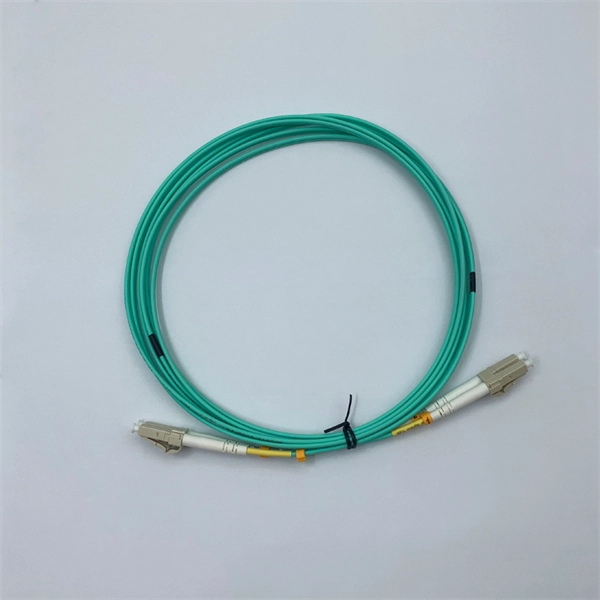
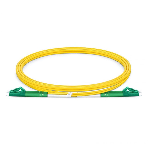
The type of fiber optic cable and the fibers in the cable should be chosen appropriate for the type of communications system(s) being supported, the type of installation and the environment in which the
G:FIBOCO00 SAFTFiber Optic Standards Manuals2022
These specifications represent a collection of safe working processes, best practices and procedures that are annually reviewed and updated as an integral component of the Railroad''s fiber optic program.
Fiber Optic Cable Installation Method Statement
Below is given the fiber optic cable installation method statement for performing the installation of optical fiber cabling system for any kind and size of project.
Standard for Installing and Testing Fiber Optics
Although most fiber optic cables are not conductive, any metallic hardware used in fiber optic cabling systems (such as wall-mounted termination boxes, racks, and patch panels) must be grounded.
Optical Power Meters & Sources
High-precision power meters (Ge/InGaAs) and stabilized light sources for insertion loss and return loss testing.
OTDR & Fiber Characterization
Full-featured OTDR, fiber OTDR testers, and modular OTDR test modules for network deployment and troubleshooting.
OSA & Eye Diagram Analyzer
High-resolution OSA for DWDM and eye diagram testers for signal integrity validation.
BERT & Endface Inspection
BERT up to 800G, fiber endface inspection probes, and extinction ratio meters for comprehensive testing.