RF Transmitter and Receiver Circuit Diagram
Circuit Diagram of RF Transmitter and Receiver: The complete circuit Diagram including the Transmitter and Receiver part for this project is shown in the images below.
Radio Frequency Block Diagrams | RF, Microwave and
The Pasternack collection of transceiver block diagrams, including RF transceiver, transmit receiver, typical transceiver, typical transceiver and transponder wireless transceiver, allow designers to
Radio Transmitter and Receiver | Working | Block Diagram
The article provides an overview of the basic working principles of a radio transmitter and receiver, covering key components, signal processing methods, and types of wave propagation.
Rf Transmitter Circuit Diagram
Have you ever come across the mysterious yet intriguing circuit diagram of an RF transmitter? This technology has been around for decades, yet because of its complexity it remains a
A Diagram of an Rf Transmitter and Receiver Circuit
Learn how to build an RF transmitter and receiver circuit diagram with our easy-to-follow guide. Transmit and receive data wirelessly with this simple circuit.
Schematics
The secret schematics vault is here. Featuring AM transmitters, FM transmitters, VCO, limiter, stereo, RDS encoder and other schematics.
How to Build an Rf Transmitter and Receiver: A
Learn about the block diagram of an RF transmitter and receiver, including the different components and their functions in the wireless communication system.
RF Radio Frequency Transmitter Circuits
Easy 2 Meter Transmitter: This project is a simple transmitter using only one crystal and will cover 145.00 to 146.00 MHz. The crystal is a 44.9333 MHz crystal for 145.500 receive, as used in the Trio
FM Transmitter circuits with schematic diagrams
Today I thought of listing all of them here as a single web page, so anyone can easily navigate through all the radio transmitter circuits and its schematic diagrams.
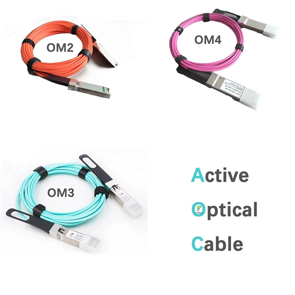
The FOA Reference For Fiber Optics
The transmitter takes an electrical input and converts it to an optical output from a laser diode or LED. The light from the transmitter is coupled into the fiber with a connector and is transmitted through the
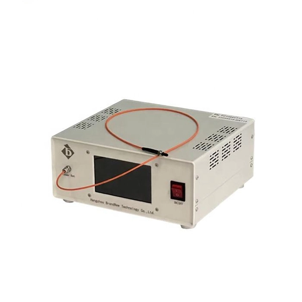
Optical Power Meters & Sources
High-precision power meters (Ge/InGaAs) and stabilized light sources for insertion loss and return loss testing.
OTDR & Fiber Characterization
Full-featured OTDR, fiber OTDR testers, and modular OTDR test modules for network deployment and troubleshooting.
OSA & Eye Diagram Analyzer
High-resolution OSA for DWDM and eye diagram testers for signal integrity validation.
BERT & Endface Inspection
BERT up to 800G, fiber endface inspection probes, and extinction ratio meters for comprehensive testing.