Cable Tray Sizing Calculator | IEC 61537 & NEC 392 Guide
Enter the width and depth of the tray that can be used. Usable depth is the space inside the tray that is available for cables to fit after taking into account the tray profile and installation
How to Measure and Install a 45-Degree Angled Tee for Cable Tray
How to Measure and Install a 45-Degree Angled Tee for Cable Tray #CableTray #45DegreeTee #ElectricalEngineering #ConstructionTips #DIYInstallation
Cable Tray Make Offset ! 45 Degree Offset Bend Formula
Make cable tray 45 Degree Offset Bend. Distance of 145 mm × 1.414 = 205 mm.Let us know what you think of this video after watching it, either by commentin...
ADVANCED S PRODUCTS I ASP 45° Turn Cable Tray
Attach Cable Trays to Cable Tray Supports and connect to other Cable Trays with splice clamps to form continuous system. Adjust height of each Cable Tray Support and correct height if necessary.
Cable Tray Size Chart and Selection Guide
Cable tray width represents the inside measurement between the longitudinal side rails and is the primary dimension that determines cable capacity. Standard electrical cable tray dimensions
Cable Bending Radius in Cable Tray | Information by Electrical
Assume a 90°, 45°, 45° triangle with the hypotenuse running out from the inside of the corner of the tray. If you run the inside of the first cable about 8.6" from the tray, you can get a 12.2"
Fiberglass cable tray 45 degree vertical outside bend assembly
THIS DRAWING AND/OR THE TECHNICAL INFORMATION CONTAINED HEREON IS THE PROPERTY OF EATON CORPORATION ("EATON"), AND IS ISSUED IN CONFIDENCE FOR
Cable Tray Offset Calculator | Vertical, Horizontal & Compound Offset
Cable Tray Bend Offset Calculator Calculate horizontal, vertical, or compound cable tray offsets based on bend angle, offset distance, and available installation space.

Cable Tray Bend Calculator
To create a 45-degree bend, cut the side rails to remove a segment calculated by the formula (Tan (22.5°) × Width). Alternatively, use a pre-fabricated 45-degree fitting with a radius sufficient for your
Cable Tray Design and Components Guide
Tables list standard sizes and specifications for straight and bent cable trays, including width, height, thickness, materials, and finishes. Drawings show
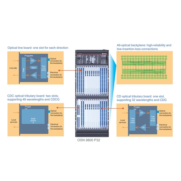
Optical Power Meters & Sources
High-precision power meters (Ge/InGaAs) and stabilized light sources for insertion loss and return loss testing.
OTDR & Fiber Characterization
Full-featured OTDR, fiber OTDR testers, and modular OTDR test modules for network deployment and troubleshooting.
OSA & Eye Diagram Analyzer
High-resolution OSA for DWDM and eye diagram testers for signal integrity validation.
BERT & Endface Inspection
BERT up to 800G, fiber endface inspection probes, and extinction ratio meters for comprehensive testing.