FIBERONE: Fiber Optic Splitter Overview | 2026
For instance, a 1×4 split configuration would take a single light beam and split it into four separate light beams to be transmitted through four individual fiber cables, as illustrated in this graphic courtesy of
What are Beamsplitters?
This is defined as the ratio of transmitted p-polarized light to s-polarized light, or Tp/Ts. However, it is important to recognize that Tp/Ts is not usually equal to the ratio of reflected s-polarized light to p
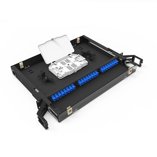
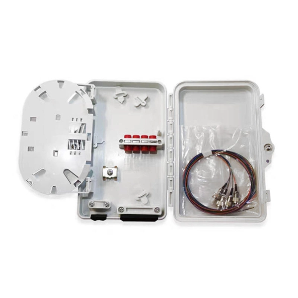
Fiber Optic Splitter 1x4
The Fiber Optic Splitter 1×4 consists of 1 input and 4 output fibers, ensuring a consistent split ratio across all fibers, regardless of the input wavelength. These splitters are available with 900µm loose
Optical Splitters: Split Ratios, Splitting Architectures & PON Network
The cascaded approach uses multiple splitters in “stages” to divide the signal—for example, a 1:4 splitter (Stage 1) feeds four 1:8 splitters (Stage 2), resulting in a total split ratio of 1:32.

What is PLC splitter?
The 1×4 split configuration presented below is the basic structure: separating an incident light beam from a single input fiber cable into four light beams and transmitting them through four
1x4 PLC Fiber Optic Splitter
PLC Splitters are Singlemode splitters with an even split ratio from one input fiber to multiple output fibers. This PLC Splitter is a 1x4, with 1 input and 4 output fibers with an even split ratio across all
Beam splitter
To reduce loss of light due to absorption by the reflective coating, so-called "Swiss-cheese" beam-splitter mirrors have been used. Originally, these were sheets of highly polished metal perforated with
Fiber Optic Splitters for PON Networks: 2025 Guide
One component makes PON deployment scalable and efficient: the fiber optic splitter. It allows a single input from the OLT to serve multiple endpoints without active electronics.
Beam Splitters – optical power splitter, beamsplitter, thin
While most beam splitters have a fixed splitting ratio, variable beam splitters allow for the continuous adjustment of the ratio between reflected and transmitted power.
Basic Knowledge about Split Ratio and Insertion Loss of Optical Splitter
The splitter ratio in fiber optic networks refers to how optical power is distributed among the output ports of an optical splitter. Expressed as a ratio or percentage, the splitter ratio indicates
Optical Power Meters & Sources
High-precision power meters (Ge/InGaAs) and stabilized light sources for insertion loss and return loss testing.
OTDR & Fiber Characterization
Full-featured OTDR, fiber OTDR testers, and modular OTDR test modules for network deployment and troubleshooting.
OSA & Eye Diagram Analyzer
High-resolution OSA for DWDM and eye diagram testers for signal integrity validation.
BERT & Endface Inspection
BERT up to 800G, fiber endface inspection probes, and extinction ratio meters for comprehensive testing.