
Fiber Loss Limits – How Much Loss Is Too Much in
When two fiber ends are joined—either by fusion splicing or mechanical splicing—some signal loss occurs. Fusion splices are more accurate
Understanding Splice Loss: Causes and Fixes – DBtek
While some loss is unavoidable, excessive loss can compromise network performance. Understanding its causes and solutions is critical for reliable fiber optic installations.
Fiber Splice Loss Calculator
Estimate fiber splice, connector, and cable attenuation losses. Compare totals against equipment power budget for reliability. Export results to reports and validate field designs quickly.
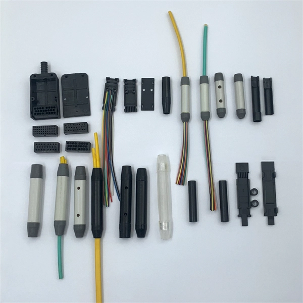
The principle of optical fiber cold splice technology
Minimal fiber loss: Cold splicing typically results in minimal fiber loss, which means that the quality of the signal is not compromised. This is important in situations where the integrity of the
Guidelines On What Loss To Expect When Testing
The uncertainty of the loss test is probably in the same range, so the actual loss is in the range of 7.7 to 8.7dB. Thus there is considerable overlap of the loss budget
Fiber Optic Cabling Loss Limits Explained – Trend Networks
Learn about fiber optic cabling loss limits & how to calculate them. Gain insights from experts on acceptable loss for cabling projects & explore the standards.
What Is the Typical Splice Loss in a Fusion Splice? | CMW
Learn about typical splice loss in fusion splicing, what''s considered acceptable, and how to minimise loss in your fibre optic network.
Understanding Fiber Loss: What Is It and How to Calculate It?
This post introduces the main fiber loss types, the calculation process of link loss including fiber attenuation, connector loss, and splice loss, calculating power budget and calculating
Fiber Optic Splicing: Examining the Factors that Affect
Learn the the intrinsic and extrinsic factors that can impact fiber optic splice performance and how you can create the best fiber optic network.
Guidelines On What Loss To Expect When Testing Fiber Optic Cables
The uncertainty of the loss test is probably in the same range, so the actual loss is in the range of 7.7 to 8.7dB. Thus there is considerable overlap of the loss budget and the measurement results, so there
Fiber Loss Limits – How Much Loss Is Too Much in Fiber Optic Testing?
When two fiber ends are joined—either by fusion splicing or mechanical splicing—some signal loss occurs. Fusion splices are more accurate and generally introduce less loss (typically < 0.1
Factors affecting fiber splice loss and how to reduce it
Fiber splice loss measures how much signal drops when you join two fiber ends. You want low splice loss because signal loss can weaken communication and reliability.
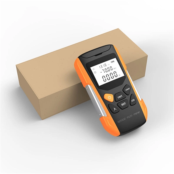
Optical Power Meters & Sources
High-precision power meters (Ge/InGaAs) and stabilized light sources for insertion loss and return loss testing.
OTDR & Fiber Characterization
Full-featured OTDR, fiber OTDR testers, and modular OTDR test modules for network deployment and troubleshooting.
OSA & Eye Diagram Analyzer
High-resolution OSA for DWDM and eye diagram testers for signal integrity validation.
BERT & Endface Inspection
BERT up to 800G, fiber endface inspection probes, and extinction ratio meters for comprehensive testing.