How to Calculate Optical Splitter Loss
Calculating optical splitter loss is more than just a single formula. It involves understanding the fundamental physics of light splitting, recognizing the real-world limitations
How beam splitters affect signal attenuation and polarization
In the context of beam splitters, attenuation can occur due to several factors, including absorption, reflection, and scattering. When a beam splitter divides the incoming light, some of the
Beam Splitters — Abridged Guide
When comparing beam splitters, always check whether the specified R/T ratio is for unpolarized light or for a specific polarization. The numbers can differ significantly.
Beam splitter
To reduce loss of light due to absorption by the reflective coating, so-called "Swiss-cheese" beam-splitter mirrors have been used. Originally, these were sheets of highly polished metal perforated with
Understanding Optical Splitter Loss
Insertion loss tells you how much weaker the signal becomes after passing through the splitter. Let''s say you have a laser output at 0 dBm (which is 1 milliwatt of optical power).
Optical Splitter Loss Calculator
This calculator helps construction and commissioning teams document expected attenuation before pulling, terminating, and testing fiber. Start with the theoretical split loss, which depends only on the
Beam Splitters – optical power splitter, beamsplitter, thin-film
A beam splitter (or beamsplitter, power splitter) is an optical device which can split an incident light beam (e.g. a laser beam) into two (or sometimes more) beams, which may or may not have the same
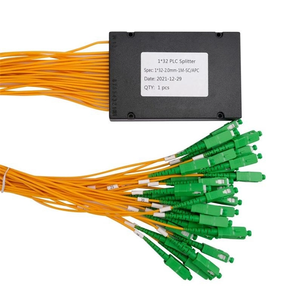
Optical Splitter Insertion Loss Table | PDF | Electronic Engineering
The document contains tables listing the insertion loss in dBm for various splitting ratios of an optical splitter, ranging from 1% to 99%. It also includes formulas for calculating insertion loss based on the
Beam Splitter
A beam splitter is then used to pick off a small portion (2–10%) of the beam to sample the profile before passing the energy across two additional beam-turning mirrors and into a focusing lens.
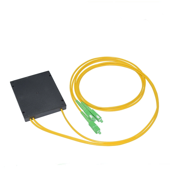
PON crib: splitters, ratios, gains, losses
A very frequent question is how the splitter ratio in an optical splitter relates to the actual signal gain. In other words, how much attenuation a splitter contributes to each output.
Optical Power Meters & Sources
High-precision power meters (Ge/InGaAs) and stabilized light sources for insertion loss and return loss testing.
OTDR & Fiber Characterization
Full-featured OTDR, fiber OTDR testers, and modular OTDR test modules for network deployment and troubleshooting.
OSA & Eye Diagram Analyzer
High-resolution OSA for DWDM and eye diagram testers for signal integrity validation.
BERT & Endface Inspection
BERT up to 800G, fiber endface inspection probes, and extinction ratio meters for comprehensive testing.