Cable tray install | Information by Electrical Professionals for
In general, vertical spacing for cable trays should be 30 cm (12 in), measured from the bottom of the upper tray to the top of the lower tray. A minimum clearance of 23 cm (9 in) should be
Method Statement installation of Cable Trays and Ladders
The Cable Tray system is installed in electrical rooms, plant rooms, and service corridors. This section will guide you through the necessary steps to ensure a successful installation.
Cable Tray Installation
Whether you''re building a commercial setup or upgrading an industrial plant, proper cable tray installation ensures neat wiring, safe access, and easy maintenance. But before you lay the first tray
Best Practice Guide to Cable Ladder and Cable Tray Systems
This publication is intended as a practical guide for the proper and safe* installation of cable ladder systems, cable tray systems, channel support systems and associated supports.
Best practice guide to cable ladder and cable tray systems | EEP
The following recommendations are intended to be a practical guide to ensure the safe and proper installation of cable ladder and cable tray systems and channel support and other support
Cable Tray Installation Method Statement
Below is the detailed cable tray installation method statement not only for cable tray but also applicable for GI ladder and trunking for indoor and outdoor applications and in service rooms like pump rooms,
Cable Tray Installation
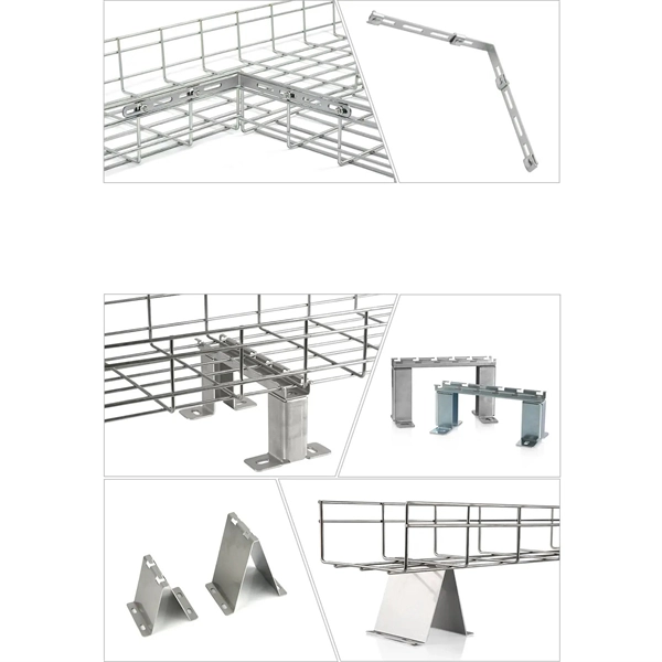
Proper planning for installing cable tray includes calculations based on loading, support systems, cable/wire fill and spacing, conductor types, securing of the cables and wire, and proper grounding
Cable Tray Technical Guide A practical guide to product selection
Cable tray length is selected based on the load to be supported, the distance between the supports (also referred to as the span), and handling and installation constraints.
Cable Slack Management Trays Cable Management and Racks 227
The sliding tray model features a sliding tray, sliding cable entrance radius guides, a removable door, and a larger footprint for increased slack storage capacity.
A Guide to Installing and Supporting Electrical Cable Trays
This guide covers the critical steps, from selecting the right electrical cable tray and performing accurate cable fill calculations to managing a safe cable pull through and ensuring all bonding and grounding
Best practice guide to cable ladder and cable tray
The following recommendations are intended to be a practical
B-Line series Cable Tray Design Considerations
Our wind certification report provides you with list of acceptable B-Line series cable tray supports, fittings and covers based off of the environmental conditions, cable loading, and type of cable tray in your
Optical Power Meters & Sources
High-precision power meters (Ge/InGaAs) and stabilized light sources for insertion loss and return loss testing.
OTDR & Fiber Characterization
Full-featured OTDR, fiber OTDR testers, and modular OTDR test modules for network deployment and troubleshooting.
OSA & Eye Diagram Analyzer
High-resolution OSA for DWDM and eye diagram testers for signal integrity validation.
BERT & Endface Inspection
BERT up to 800G, fiber endface inspection probes, and extinction ratio meters for comprehensive testing.