The FOA Reference For Fiber Optics -Outside Plant Construction
Deploying fiber above ground on poles or towers removes the need for underground digging and is particularly useful when the ground is uneven, rocky or both. Aerial installation is generally much less
Overhead Fiber Optic Cable Installation: Requirements
This comprehensive guide delves into the installation requirements, explores the two primary cable types—self-supporting and messenger-supported—and offers
FOA Standard For Installing Fiber Optic Cable Plants
Support structures for fiber optic cable installations should be completed before the installation of the fiber optic cable itself. Outside plant structures should be installed in conformance with all permits
FIBER OPTIC CONSTRUCTION STANDARDS
Fiber optic cable sequential numbers are required at each pole location and vault wall. Sequential numbers will identify conduit length, and slack left in vaults and at poles.
Overhead Fiber Optic Cable Installation: Requirements & 2 Key Types
This comprehensive guide delves into the installation requirements, explores the two primary cable types—self-supporting and messenger-supported—and offers practical insights to ensure optimal
Overhead Optical Cable Construction Guidelines
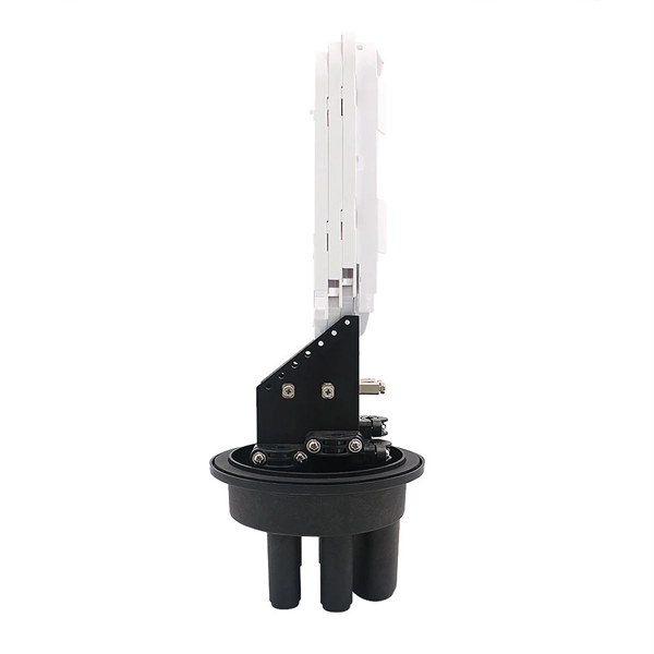
The discharge terminal, corner pole, crossing pole, branch pole, slope top pole and poles above 12m must be equipped with pull-wire lightning protection grounding wires, and the suspension
Aerial Fiber Optic Cable Installation Standards
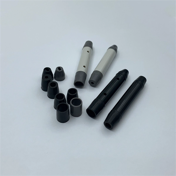
This document provides technical specifications for the aerial installation of fiber optic cable (FOC) networks. It outlines PLDT standards for pole line hardware, including concrete poles, pole clamps,
Requirements for the Attachment of Communication Cable
Use Section 23 of the NESC to determine the clearances required at the pole and in-span. It specifies that the required vertical clearances must be measured surface-to-surface, not center-to-center.
COMMUNICATION CONDUCTORS UNDER 12KV
THE MAXIMUM HEIGHT OF COMMUNICATION CABLE ABOVE GROUND FOR STANDARD DELTA FRAMING ON 50'' POLE IS 20''-8" AND VERTICAL FRAMING ON 55'' POLE IS 21''-0" (SEE NOTE 1).
INSTALLATION OF AERIAL FIBRE OPTIC CABLES
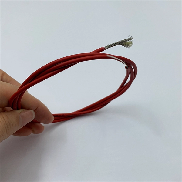
It is important when installing aerial optical fibre cable lengths to make proper arrangement for an adequate extra length of cable at a pole position for testing and jointing.
Lashed Aerial Installation of Fiber Optic Cable
cables that may sag near the fiber optic cable. Determine the clearances between the proposed fiber optic cable plant and existing facilities on a case-by-case basis by referring to the National Electrical
Optical Power Meters & Sources
High-precision power meters (Ge/InGaAs) and stabilized light sources for insertion loss and return loss testing.
OTDR & Fiber Characterization
Full-featured OTDR, fiber OTDR testers, and modular OTDR test modules for network deployment and troubleshooting.
OSA & Eye Diagram Analyzer
High-resolution OSA for DWDM and eye diagram testers for signal integrity validation.
BERT & Endface Inspection
BERT up to 800G, fiber endface inspection probes, and extinction ratio meters for comprehensive testing.