Automatic Gain Control (AGC) circuits
The main objective of this paper is to provide the hypothetical reader with a deep insight of the theory and design of AGC circuits ranging from audio to RF applications. We will begin studying the control
Automatic gain control
In a typical receiver, the AGC feedback control signal is usually taken from the detector stage and applied to control the gain of the IF or RF amplifier stages.
CN-0390 (Rev. 0)
The automatic gain control (AGC) circuit is useful in multiple applications such as amplitude stabilization of a synthesizer, controlling output power in a transmitter, or optimizing dynamic range in a receiver.
5. Receiver Gain and AGC
Instead, receiver designers implement an adjustable gain amplifier using one or more fixed gain amplifiers and one or more variable attenuators (e.g., digital attenuators).
How Automatic Gain Control (AGC) Works
In principle, an AGC is a feedback control system that drives the amplitude error to zero in an iterative fashion. This establishes, on average, a constant signal amplitude at the start of the
Automatic Gain Control IP User Guide
This User Guide will provide detailed instructions on configuring and utilizing the AGC IP, including parameter settings, integration tips, and troubleshooting advice. By the end of this guide, users will
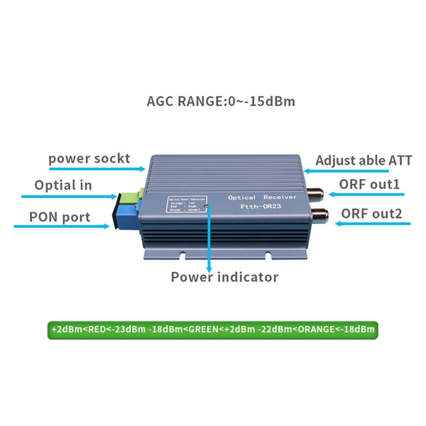
Chapter 9 Optical Receiver Design
9.1 Introduction the design of optical receivers. As signals travel in a fiber, they are attenuated and distorted, and it is the function of the receiver circuit at the other side of the fiber to generate a clean
An optical receiver with automatic gain control for radio-over-fiber
An optical receiver circuit with automatic gain control (AGC) for radio-over-fiber (RoF) system is presented. The AGC optical receiver is designed on the standa
Automatic Gain Control (AGC) in Receivers
Automatic Gain Control (AGC) circuits are employed in many systems where the amplitude of an incoming signal can vary over a wide dynamic range. The role of the AGC circuit is to provide a
Usage of the Automatic Gain Control Circuit (AGC)
The TDA520x, TDA521x, TDA522x, TDA7200, TDA7210 and TDA7210V receivers provide an AGC (Automatic Gain Control) circuit that can be used in the active mode or in the

Automatic Gain Control (AGC) in Radio Systems: Principles and
In AM receivers, AGC voltage usually goes to the intermediate frequency (IF) amplifier stages for steady control. In FM receivers, AGC still helps avoid overload, even though FM is less
Optical Power Meters & Sources
High-precision power meters (Ge/InGaAs) and stabilized light sources for insertion loss and return loss testing.
OTDR & Fiber Characterization
Full-featured OTDR, fiber OTDR testers, and modular OTDR test modules for network deployment and troubleshooting.
OSA & Eye Diagram Analyzer
High-resolution OSA for DWDM and eye diagram testers for signal integrity validation.
BERT & Endface Inspection
BERT up to 800G, fiber endface inspection probes, and extinction ratio meters for comprehensive testing.